R P9000 Series Multifunction Printer User's Reference Manual
P9000 Series Multifuction Printer User's Reference Manual R P/N 133397–001, Rev B
US and CANADA Radio Interference Note Note: This device complies with Part 15 of the FCC Rules. Operation is subject to the following two conditions: (1) this device may not cause harmful interference, and (2) this device must accept any interference received, including interference that may cause undesired operation. Properly shielded and grounded cables and connectors must be used in order to meet FCC emission limits.
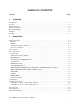
TABLE OF CONTENTS Chapter 1 Page OVERVIEW Introduction . . . . . . . . . . . . . . . . . . . . . . . . . . . . . . . . . . . . . . . . . . . . . . . . . . . . . . . . . . . . . . . . . . . . . . . . . . . . . . 1-1 Features . . . . . . . . . . . . . . . . . . . . . . . . . . . . . . . . . . . . . . . . . . . . . . . . . . . . . . . . . . . . . . . . . . . . . . . . . . . . . . . . . . 1-1 Optional Features . . . . . . . . . . . . . . . . . . . . . . . . . . . . . . . . . . . . . . . . . . . . . . . . . .
2 OPERATION (continued) Setting Forms Length . . . . . . . . . . . . . . . . . . . . . . . . . . . . . . . . . . . . . . . . . . . . . . . . . . . . . . . . . . . . . . . . . . . . . 2-16 To Set Forms Length in Inches . . . . . . . . . . . . . . . . . . . . . . . . . . . . . . . . . . . . . . . . . . . . . . . . . . . . . . . . . . . . 2-16 To Set Forms Length in Lines . . . . . . . . . . . . . . . . . . . . . . . . . . . . . . . . . . . . . . . . . . . . . . . . . . . . . . . . . . . . .
5 VERTICAL FORMAT UNITS Introduction . . . . . . . . . . . . . . . . . . . . . . . . . . . . . . . . . . . . . . . . . . . . . . . . . . . . . . . . . . . . . . . . . . . . . . . . . . . . . . 5-1 General VFU Programming . . . . . . . . . . . . . . . . . . . . . . . . . . . . . . . . . . . . . . . . . . . . . . . . . . . . . . . . . . . . . . . . . 5-1 VFU Load/Save/Clear . . . . . . . . . . . . . . . . . . . . . . . . . . . . . . . . . . . . . . . . . . . . . . . . . . . . . . . . . . . . . . . . . . . .
6 PROGRAMMING (continued) Special Function Control Code - Control Code Header . . . . . . . . . . . . . . . . . . . . . . . . . . . . . . . . . . . . . . . . . 6-2 Attribute Set and Reset Codes . . . . . . . . . . . . . . . . . . . . . . . . . . . . . . . . . . . . . . . . . . . . . . . . . . . . . . . . . . . . . . . 6-3 Control Code Reference Index . . . . . . . . . . . . . . . . . . . . . . . . . . . . . . . . . . . . . . . . . . . . . . . . . . . . . . . . . . . . . . . 6-4 Backspace . . . . . . . . .
6 PROGRAMMING (continued) Overscoring . . . . . . . . . . . . . . . . . . . . . . . . . . . . . . . . . . . . . . . . . . . . . . . . . . . . . . . . . . . . . . . . . . . . . . . . . . . . . . 6-54 Plot, Even Dot (P-Series High Density Graphics) . . . . . . . . . . . . . . . . . . . . . . . . . . . . . . . . . . . . . . . . . . . . . 6-55 Plot, Odd Dot (P-Series Normal Density Graphics) . . . . . . . . . . . . . . . . . . . . . . . . . . . . . . . . . . . . . . . . . . . 6-56 Printer Reset . . . . . . .
9 RIBBONMINDER Introduction . . . . . . . . . . . . . . . . . . . . . . . . . . . . . . . . . . . . . . . . . . . . . . . . . . . . . . . . . . . . . . . . . . . . . . . . . . . . . . 9-1 Overview . . . . . . . . . . . . . . . . . . . . . . . . . . . . . . . . . . . . . . . . . . . . . . . . . . . . . . . . . . . . . . . . . . . . . . . . . . . . . . . . . 9-1 Analyzing a Job . . . . . . . . . . . . . . . . . . . . . . . . . . . . . . . . . . . . . . . . . . . . . . . . . . . . . . . . . . . . . . . . . .
About This Manual This manual has been written and formatted in a way to make it easy for you to use. The followĆ ing is some general information about this User's Reference Manual. What This Manual Contains This manual is divided into chapters that contain all the information required to use the printer.
viii P9012 Multinational User's Reference Manual
CHAPTER 1 OVERVIEW Introduction The Printronix P9012 printer is a quiet, full-featured, multifunction line printer. In addition to the basic Printronix P-Series printer functions, the P9012 includes correspondence quality print for near-letter-quality (NLQ) printing requirements, high-speed printing, and character-by-character attributes for wide application compatibility.
n Built-in Diagnostic Self-Tests n RibbonMindert Feature n Configuration Printout n Data Stream Hex Code Printout n Resident Serial and Parallel Interfaces n Downloadable Character Sets n Downloadable Languages Two separate graphics capabilities are included in the printer: standard P-Series odd-even dot Plot Mode graphics and Bit Image graphics. Intelligent graphics capabilities are available by using the Printronix Intelligent Graphics Processor (IGP) options.
Character Formation The P9012 printer generates characters by assembling groups of dots in matrices. Dots overlap to produce a solid appearing character (Figure 1-1). Dot impressions are made by an assemĆ bly of 88 hammers installed on an oscillating shuttle. The hammers impact the paper through a moving ink ribbon. Horizontal shuttle movement and vertical paper advancement combine for precise dot printing to form the character. Figure 1-1.
DIRECTION OF SHUTTLE MOVEMENT DOT ROW ONE CHARACTER ROW 1 2 3 4 5 6 7 8 9 10 11 12 1 2 PAPER ADVANCES START PAPER FEED * ** PAPER ADVANCES SPACE 1 HAMMER PRINT SPAN * ** 1 HAMMER PRINT SPAN USED FOR LOWERCASE DESCENDER ONLY USED FOR UNDERLINE AND LOWERCASE DESCENDER NOTE: P9012 SHUTTLE SWEEPS THROUGH 1.5 CHARACTER POSITIONS AT 10 CPI Figure 1-2.
Plot Rate As well as character printing, the P9012 printer is capable of dot-addressable graphic plotting. Based on the protocol selected, either P-Series Plot Mode or Serial Matrix Bit Image GraphĆ ics is used; the plot rate specifications apply to both P-Series and Serial Matrix types of graphĆ ic plotting. The plot rate (in inches per minute, ipm," bidirectional) is described in Table 1-2 according to the dot density (in dots per inch, dpi).
1-6 Overview
CHAPTER 2 OPERATION Operation Features On Line The P9012 printer functions either on line" or off line." When on line, the printer is capable of receiving data and control commands from the host computer. The message display on the printer control panel indicates that the printer is on line and shows the current print mode. Off Line When the printer is off line, communication between the printer and the host computer is temĆ porarily stopped and the message OFFLINE READY appears on the display.
You can also define and download an international language to allow any character within the character library to be substituted for any code. Similarly, an individual character in a font, or an entire set of characters, can be created and placed in a font. These downloading features are discussed in more detail in the Programming chapter and the Appendix. Power Switch The AC power switch is located at the lower left corner of the rear panel of the printer.
STATUS LAMPS ALPHANUMERIC MESSAGE DISPLAY ON LINE ON LINE CLEAR CHECK 6/8 LPI 8 LPI PAPER ADV VFU LOADED HOLD ENABLE REPRINT PA1 CANCEL PA2 PROVIDED WITH PI-3287 OPTION ALT MODE NOTE: THESE SWITCHES ARE VISIBLE ONLY WITH THE PRINTER COVER OPEN MENU UP NEXT RUN/ STOP PRINT MODE MENU DOWN PREV ENTER F/L Figure 2-1. Control Panel ON LINE Switch Press this switch to place the printer alternately on line or off line.
CLEAR Switch and CHECK Indicator If a fault condition occurs, a fault message appears on the Message Display, and the CHECK indicator flashes alternately with the ON LINE indicator. Press the CLEAR switch to indicate to the printer that a fault condition has been corrected. After pressing CLEAR, the fault status will be validated and the display updated. If all faults were corrected, the display will indicate the printer is off line. In addition, the CLEAR switch also has the special functions noted below.
HOLD ENABLE, REPRINT PA1, CANCEL PA2, ALT MODE (Optional Switches) These four switches and their associated LEDs are included on printers equipped with a Printronix PI-3287 printer interface and operate independently of all other control panel switches. The PI-3287 enables a Printronix printer to emulate an IBM 3287 printer; the printer may then be used with an IBM 3274 or 3276 control unit. Information on the operation and function of these switches is contained in the PI-3287 User's Reference Manual.
The ENTER switch must be enabled (unlocked) before making configuration or format changes. Simultaneously pressing MENU UP and MENU DOWN alternately locks and unĆ locks the ENTER switch. (This sequence protects against accidental reconfiguration.) ResetĆ ting the printer or turning the power off and on will lock the ENTER switch. No other switches are affected by this action.
Loading Paper The P9012 printer uses standard fanfold paper from 3 to 16 inches wide and 15 to 100 lb bond (0.025 inches thick maximum). To load paper, perform the following steps and refer to Figure 2-2. 1. Place the printer off line and raise the printer cover. 2. Fully raise the Forms Thickness Adjustment Lever (A). (The CHECK indicator will light, the status lamps will flash alternately, and the display will indicate a platen open condiĆ tion). 3. Open both tractor gates (B) by swinging them out.
Figure 2-2.
Setting Top-Of-Form Top-of-form determines where the first line of print will appear and is set when paper is loaded. Typically, the first line of print is set approximately one-half inch below the paper perĆ foration unless specific application requirements dictate otherwise. Once top-of-form has been set, the paper can be advanced to the top of the next form by pressing the PAPER ADV switch. Unless otherwise configured, the P9012 printer assumes 11-inch length paper is used.
Figure 2-3. Setting Top-of-Form Setting Top-of-Form - Reverse Paper Motion NOTE: Do not use this method of setting top-of-form for heavy forms or peel-off laĆ bel forms. 1. Place the printer off line and raise the printer cover. 2. Move the Forms Thickness Adjustment Lever to the fully open position. (The CHECK indicator will light, the status lamps will flash alternately, and FAULT CONDITION PLATEN OPEN will be displayed.) 3.
Paper Stacking The printer can stack at least half a box of standard computer paper when the paper is properly loaded. After loading the paper, perform the following steps. 1. Open the rear cabinet door to access the paper stacking area. NOTE: Step 2 pertains to installation of the front paper stacking fence. (The rear fence on the rear cabinet door is installed at the factory.) If the front fence has already been installed, continue with the paper stacking instructions at step 3. 2.
NOTE 4: Check that the chains are properly installed (see Installation chapter) and that they engage the paper. Figure 2-4.
Figure 2-5. Paper Tent Installation Figure 2-6.
Unloading Paper 1. Place the printer off line and raise the printer cover. 2. Tear off the paper below the paper slot. 3. Fully raise the Forms Thickness Adjustment Lever. 4. Open both tractor gates and remove the paper from the tractor sprockets. 5. Gently pull the paper up through the paper slot. Be careful not to let paper perforations or sprocket holes catch on the ribbon mask. Replacing The Ribbon Each printer is shipped with a standard black ink, one-inch nylon fabric ribbon on two spools.
Figure 2-7. Ribbon Replacement 7. Lower the Forms Thickness Adjustment Lever (A) to the appropriate operating position. 8. Press CLEAR (on the control panel) to clear the PLATEN OPEN fault condition. 9. Close the printer cover and place the printer on line.
Setting Forms Length NOTE: Forms length can also be set by control code from the host computer which will override the control panel setting. Using control codes, the host computer can specify forms lengths other than those available from the control panel. Refer to the ProgramĆ ming chapter for more information. The printer uses continuous, tractor-fed paper with the forms length set between 1.0 and 24.0 inches, or between 1 and 192 lines at 6 or 8 lines per inch.
2. Press MENU DOWN to display the current forms length in lines. 3. Press NEXT or PREV to increase or decrease the forms length in 1-line increments, reĆ spectively. When the appropriate value is displayed, save it as described below. 4. Press ENTER to select the displayed forms length. 5. Press CLEAR to return to OFFLINE READY. 6. Simultaneously press MENU UP and MENU DOWN to lock the printer configuration. 7. Set the top of form according the the instructions on page 2-9. 8.
For additional printing capabilities and character attributes, refer to the Programming chapĆ ter. Print mode control from the host will override the control panel setting. Setting Line Spacing P9012 printers can be set for a line spacing of 6, 8, or 10.3 lines per inch (lpi) from the control panel by using the 6/8 LPI switch. To select the line spacing from the control panel, perform the following procedure. 1. Place the printer off line. 2.
3. Press MENU DOWN, then repeatedly press NEXT or PREV until the PRINT DATA STREAM IN HEX CODE message is displayed. 4. Press MENU DOWN; the display will show OFFLINE HEX DUMP. 5. Press ON LINE. The display will indicate that the printer is on line and in hex dump mode. 6. Send the data from the host; the hex dump will print. 7. Press ON LINE again to stop the hex dump. The display will read OFFLINE HEX DUMP. 8. Press CLEAR to return printer to OFFLINE READY. 9.
Fault Condition Messages If a fault condition occurs in the printer, the CHECK light illuminates, the status lamps blink alternately, and the first line of the message display reads FAULT CONDITION. If confiĆ gured, an alarm will sound when the Fault Condition occurs. The second line of the display will show the specific fault. (If the specific fault description requires two lines, the message FAULT CONDITION will not be shown.
Field Service Required Printer problems requiring the attention of an authorized service representative also appear on the second line of the display and are indicated by an asterisk (*) next to the message: PROGRAM PROM * NOVRAM * FONT PROM * HAMMER DR PCB X * ( X = 1, 2, or 3 ) If HAMMER DR PCB X * appears on the display, printer power will automatically shut off 10 seconds after the fault message is displayed.
2-22 Operation
CHAPTER 3 CONFIGURATION Introduction Configuration refers to the set of operating parameters that define how the printer communiĆ cates with the host computer. Most configuration parameters are selected from the control panel, as shown in the Control Panel Configuration Diagram at the end of this chapter. Some configuration parameters are hardware selectable by installing jumpers on the DCU board, as described in Appendix F.
From the main configuration menus below, related configuration parameter values can be disĆ played and selected. D Ribbon Life xxx% D Character Set D Application Compatibility D Paper Format D Host Interface D Load Parameters D Save Parameters D Diagnostics NOTE: The xxx% in the Ribbon Life menu will not be displayed in the LCD message if the RibbonMinder feature is disabled.
Figure 3-1.
Factory Default Configuration Values Printronix factory default configuration values are shown in Table 3-1. These values are operaĆ tional when the printer is received. New values can be saved and applied as necessary for each application, but factory default values remain accessible using the LOAD PARAMETERS menu. On the Control Panel Configuration Diagrams, factory configuration values are indiĆ cated by an asterisk (*). (The asterisk is not shown on the printer display.) Table 3-1.
Configuration Procedure Most configuration options are selected from the control panel menu. To change the configuraĆ tion from the control panel, the printer must be powered up, off line (OFFLINE READY), and the control panel ENTER switch enabled (unlocked). The current configuration may be examĆ ined - but not changed - by leaving the ENTER switch locked. The basic configuration procedure requires pressing MENU DOWN and NEXT/PREV to arĆ rive at the desired menu.
Load Configuration Values The previously saved default value set or the permanently stored Printronix factory value set can be loaded for use as needed. The following procedure provides a convenient method of resetting the printer configuration to a known value set. 3-6 1. Place the printer off line and raise the printer cover. Enable the ENTER switch by pressĆ ing MENU UP and MENU DOWN simultaneously. ENTER SWITCH NOT LOCKED will temporarily appear in the LCD message display. 2.
Control Panel Configuration Diagram The Control Panel Configuration Diagram is a series of block diagrams that show the configuĆ ration menus and the parameters (values) available within each menu. The boxes represent the message display, the message that appears on the display is printed inside the box, and the letĆ ters outside the boxes adjacent to the directional arrows represent control panel switches. When a switch is pressed, an arrow leads to the displayed result of pressing that switch.
Level III - Configuration Menu Parameters (Continued) 3-8 Auto Line Feed Define CR Code Define LF Code VFU Select VFU Table (Save/Clear) Perforation Skip Paper Out PMD Fault Print Width Centronics Interface Parameters Dataproducts Interface Parameters Serial RS-232 Interface Parameters Data Bit 8 PI Line Data Polarity Response Polarity Fast Busy Strobe Polarity Latch Data On Data Protocol Data Rate Word Length Stop Bit Parity Bit 8 Function CD and DSR CTS and DSR Data Term Ready Request To Send Reverse
CONTROL PANEL CONFIGURATION DIAGRAM SYMBOLS: CONTROL PANEL MESSAGE DISPLAY OL = Press STATUS LAMPS ON LINE CL = Press CLEAR LS = Press 6/8 LPI MENU DOWN D = Press U = Press MENU UP N = Press NEXT P = Press PREV RUN/ STOP RS = Press E = Press ENTER ALPHANUMERIC MESSAGE DISPLAY ON LINE ON LINE CLEAR CHECK 6/8 LPI 8 LPI PAPER ADV VFU LOADED HOLD ENABLE REPRINT PA1 CANCEL PA2 PROVIDED WITH PI-3287 OPTION ALT MODE PM = Press PRINT MODE FL = Press F/L + = Press switches simulta
ON LINE DP AT 10 CPI Pressing MENU UP and MENU DOWN simultaneously will alternately lock/ unlock the ENTER switch. ENTER SWITCH NOT LOCKED or ENTER SWITCH LOCKED will appear on the display for 1 second . * , Factory print mode setting shown for illustration only. Print mode is an option set by the user. OL OL U+D , OFFLINE READY NOTE: Press OL in any submenu (except when diagnostic tests are running) to enter the ON LINE state.
Configuration 3–11 LS or N P LS or N LINE SPACING SET AT 10.3 LPI P * LS or N LINE SPACING SET AT 8 LPI P LINE SPACING SET AT 6 LPI CL CL N P NLQ AT 10 CPI NLQ AT 12 CPI NLQ AT 15 CPI CL CL CL P FL U U N or FL P FORMS LENGTH SET AT 10.5 INCHES U N or FL FORMS LENGTH RANGE IS FROM 1.0 TO 24.0 INCHES IN 0.5 INCH INCREMENTS P N or FL * D or FL (1) FORMS LENGTH SET AT 11.
3–12 Configuration P U or CL OL SHEET 3 A D U RIBBON LIFE xxx % D OFFLINE READY ON LINE DP AT 10 CPI N P P SHEET 4 B D CHARACTER SET U N P SHEET 5 C D U U or CL APPLICATION COMPATIBILITY N P U or CL SHEET 8 D D U PAPER FORMAT N N P U or CL U or CL SHEET 15 G D DIAGNOSTICS U U SHEET 10 E D HOST INTERFACE Control Panel Configuration Diagram (sheet 2 of 17) U or CL NOTE: If configuration changes are to be made, unlock the ENTER switch at this point by simulta
Configuration 3–13 P U Press the ENTER switch to reset ribbon life to 100%.
3–14 Configuration N P * U (1) P N (2)(3) P SELECT LANGUAGE LATIN AM P N FRENCH GERMAN ENGLISH U DANISH SWEDISH ITALIAN SPANISH JAPANESE FRENCH CANADIAN * U SELECT LANGUAGE ASCII D SELECT SET IBM PC D CHARACTER SET B FROM SHEET 21 N P U * U (4) (2)(3) N N P P N U U * U N P N U P N * N N (5) EXTENDED SUBSET is DEC MULTINATIONAL U N (2) (3) N SELECT LANGUAGE SWISS P FINNISH DUTCH FRENCH CANADIAN JAPANESE ITALIAN SPANISH SWEDISH NOR./DAN.
Configuration 3–15 N or P PRINTER PROTOCOL P–SERIES * PROTOCOL U PRINTER PROTOCOL SERIAL MATRIX U D PRINTER U P N N P P BUFFER SIZE 1024 CHARACTERS P BUFFER SIZE 512 CHARACTERS P BUFFER SIZE 2048 CHARACTERS D BUFFER SIZE U N N U U U * (1) PRINTER SELECT ON=DC1 / OFF=DC3 N or P PRINTER SELECT DISABLE D PRINTER SELECT U APPLICATION COMPATIBILITY U U N P * U U N P U * POWER ON STATE OFFLINE N or P POWER ON STATE ON LINE D POWER ON STATE (1) Menu available in
3–16 Configuration * N P U * P N P U (1) U P U * U P U N D Press N or P to increase/decrease seconds in 5–second increments from 4 seconds to 300 seconds SHUTTLE TIMEOUT 4 SECONDS U SHUTTLE TIMEOUT P N N N U U U N * N N N N SELECT SFCC 7E TILDE P SELECT SFCC 5E HAT P SELECT SFCC 1B ESC P SELECT SFCC 03 ETX P SELECT SFCC 01 SOH D SELECT SFCC U U U U N (1) U N CONTROL CODE 06 10.3 LPI N or P CONTROL CODE 06 8.
Configuration 3–17 Continued from sheet 6 P N U (1) N P * (1) U U N P OVERSTRIKE DISABLE OVERSTRIKE ENABLE OVERSTRIKE U N or P D * U U N P N P N N N DISPLAY LANGUAGE SPANISH P DISPLAY LANGUAGE FRENCH P DISPLAY LANGUAGE GERMAN P DISPLAY LANGUAGE ENGLISH D DISPLAY LANGUAGE U * U U U U Control Panel Configuration Diagram (sheet 7 of 17) Menu available in P–Series protocol CONTROL CODE 08 BACKSPACE N or P CONTROL CODE 08 DOUBLE HIGH D CONTROL CODE 08 U
3–18 Configuration AUTO LINE FEED DISABLE N or P AUTO LINE FEED AFTER FULL LINE D AUTO LINE FEED U * U P N P * DEFINE CR CODE CR = CR + LF N or P DEFINE CR CODE CR = CR D DEFINE CR CODE U U * (1) DEFINE LF CODE LF = LF N or P DEFINE LF CODE LF = CR + LF U D DEFINE LF CODE U N N P P PAPER FORMAT P P P P * VFU SELECT DISABLE VFU SELECT CVFU VFU SELECT NVFU VFU SELECT DVFU VFU SELECT EVFU D VFU SELECT U D N N N N (2) U U U U U N P FROM SHEET 2 U U
Configuration 3–19 P N U N N P P Continued from sheet 8 U * (1) N N N N U N P U PAPER OUT IMMEDIATE N or P PAPER OUT END OF PAPER D PAPER OUT * (1) U N P U * N or P U N P U * PRINT WIDTH 8.0 PRINT WIDTH 13.2 D PRINT WIDTH N or P U N P If a DVFU is enabled and loaded, then DISABLE and ENABLE will be the only menu boxes displayed. If the P–Series protocol EVFU, NVFU, or CVFU is enabled and loaded, then DISABLED BY VFU will be displayed.
3–20 Configuration P D DATA BIT 8 DISABLE DATA BIT 8 ENABLE D DATA BIT 8 P U N or P * U U N P * HOST INTERFACE CENTRONICS D HOST INTERFACE U H N U N P * DATA POLARITY INVERTED N or P DATA POLARITY STANDARD D DATA POLARITY U P I P U N U U RESP. POLARITY INVERTED FAST BUSY DISABLE N or P N or P FAST BUSY ENABLE D FAST BUSY U * U N P * RESP. POLARITY STANDARD D RESP.
Configuration 3–21 DATA BIT 8 DISABLE DATA BIT 8 ENABLE D DATA BIT 8 D * N or P U HOST INTERFACE DATAPRODUCTS P U N P PI LINE DISABLE D PI LINE U U N P * DATA POLARITY INVERTED N or P DATA POLARITY STANDARD D DATA POLARITY U U N P * RESP. POLARITY INVERTED N or P RESP. POLARITY STANDARD D RESP.
3–22 Configuration N U D DATA PROTOCOL DATA PROTOCOL DTR, RC, OR RTS P DATA PROTOCOL ETX / ACK P DATA PROTOCOL ACK / NAK P DATA PROTOCOL X–ON / X–OFF P D HOST INTERFACE SERIAL RS–232 N N N * U P N I N P P U * N N N N N N N U N P U N or P WORD LENGTH 7 BITS * WORD LENGTH 8 BITS D WORD LENGTH U N P U STOP BIT TWO * STOP BIT ONE D STOP BIT N or P U N Control Panel Configuration Diagram (sheet 12 of 17) DATA RATE 19200 BAUD P DATA RATE 9600 BAUD P DA
Configuration 3–23 Continued from sheet 12 N U * U N P U D U N P U U N P N D N N CD AND DSR ENABLE * CD AND DSR DISABLE CD AND DSR N or P CTS AND DSR ENABLE * CTS AND DSR DISABLE N or P D CTS AND DSR Control Panel Configuration Diagram (sheet 13 of 17) (1) Not applicable for a 7–bit word (NOT APPLICABLE displayed when appropriate) Bit 8 will be received and acted on as a zero BIT 8 FUNCTION IGNORE P BIT 8 FUNCTION PI LINE P BIT 8 FUNCTION FONT SELECT P (1) BIT 8 FUNCT
3–24 Configuration Continued from sheet 13 P N U N P N P U N N N * U N P P N N REQUEST TO SEND TRUE P REQUEST TO SEND FALSE P REQUEST TO SEND OFFLINE OR BF N REQUEST TO SEND ONLINE AND BNF D BF = BUFFER FULL BNF = BUFFER NOT FULL N P U REQUEST TO SEND * U N P Control Panel Configuration Diagram (sheet 14 of 17) DATA TERM RDY TRUE P DATA TERM RDY FALSE P DATA TERM RDY OFFLINE OR BF P DATA TERM RDY ONLINE AND BNF D DATA TERM READY N U P P N N REVERSE CHANNE
Configuration 3–25 P U P N P U ON LINE HEX DUMP OFF LINE HEX DUMP D RUNNING TEST ALL E’S RS OL PRINT DATASTREAM IN HEX CODE U FROM SHEET 2 PRINTER TEST ALL E’S N P G U N P U U D PRINTER TEST 8 INCH WIDTH RUNNING TEST E PLUS TOF RS PRINTER TEST E PLUS TOF N P U N P U U D PRINTER TEST FULL WIDTH RUNNING TEST ALL H’S RS PRINTER TEST ALL H’S N P U N N P U U RUNNING TEST DEMO RS PRINTER TEST DEMO U RUNNING TEST UNDERLINE ONLY RS J P N N P U SHEET 17
3–26 Configuration User defined LOAD SAVED COMPLETED E LOAD SAVED PARAMETERS D U LOAD PARAMETERS F FROM SHEET 2 (1) P N P U (1) N P U (1) (1) Returns after 1 second PI Line: Enable 80–9F Hex: Printable Character Set: Multinational Auto Line Feed: Disable Same as FACTORY PARAMETERS except: LOAD IBM 5225 COMPLETED E LOAD IBM 5225 PARAMETERS Control Panel Configuration Diagram (sheet 16 of 17) 80–9F Hex: Printable Character Set: Multinational Auto Line Feed: Disable LOAD IBM 3287 C
Configuration 3–27 U POWER ON TIME XXXXX.X HRS D PRINT STATISTICS J FROM SHEET 15 P N P U N P U SHUTTLE STROKES XXXXXXXXXX N P U PRINT LINES XXXXXXXXXX N P Control Panel Configuration Diagram (sheet 17 of 17) PRINT TIME XXXXX.
3–28 Configuration
CHAPTER 4 GRAPHICS Introduction The printer can produce bit image graphics when in Serial Matrix protocol, and P-Series Plot Mode graphics when in P-Series protocol. You can print text and graphics on the same line only by using the bit image protocol in Serial Matrix protocol. In either mode, printing text is the default mode. Consequently, each line of graphics data must include the necessary plot mode commands to enable the printer to perform the desired graphics functions.
1st BIT IMAGE DATA BYTE 2nd BIT IMAGE DATA BYTE 7th BIT IMAGE DATA BYTE DECIMAL WEIGHTS 128 64 32 16 8 4 2 1 73 36 146 36 255 73 146 DECIMAL VALUES Figure 4-1. Bit Image Pattern Plan How Bit Image Graphics Are Produced The binary data byte bit pattern for the ASCII character A" (hex 41, decimal 65) is pictured in Figure 4-2. D If this data byte is rotated clockwise, the result is a vertical data byte pattern with the most significant bit (MSB) at the top.
8 MSB 7 6 5 4 3 MSB 2 1 8 7 6 5 4 3 2 1 MSB : Most Significant Bit Figure 4-2. Vertical Data Byte Pattern ASCII CHARACTER A DECIMAL VALUE BINARY CODE EQUIVALENT 65 128 64 32 16 8 4 2 1 = = TO VERTICALLY ROTATED DATA BYTE BIT IMAGE PATTERN MSB = Figure 4-3. Bit Image Pattern from an ASCII Character Bit Image Density Bit image graphics may be printed in different dot densities. Dot densities are selected by conĆ trol code: D D Control code ESC K selects the Single Density Mode.
the same as in the Single Density mode. Double horizontal density requires twice the number of input data bytes to print the same length line as for Single Density. PrintĆ ing double density reduces the printing speed by half. D Control code ESC Y selects the Double Speed, Double Density Mode. When the Double Density, Double Speed control code is received, the data will be printed at double the current horizontal dot density, but adjacent dots are not printed.
D At 60 dpi, Single Density = 792 bytes; Double Density = 1584 bytes Quadruple Density = 3168 bytes Data in excess of the right margin is discarded. If the auto line feed is enabled, data in excess of the right margin will cause a Line Feed (LF) and continue printing on the next line. A detailed description of the individual bit image control codes with examples is provided in the Programming chapter.
In Normal Density Plot: D The mode is selected with the odd dot plot control code ENQ (05 hex). D The odd-numbered dot columns are addressed to produce a horizontal and vertical density that varies, based on the mode of operation: Print Mode D Horizontal dpi Vertical dpi Data Processing (DP) 60 72 Correspondence (NLQ) 90 96 High Speed A (HS) 60 48 High Speed B (HSB) 60 72 High Speed C (HSC) 60 72 Different print modes cannot be mixed on the same dot row.
Plot Data Byte Format In P-Series Plot Mode, the format is as follows: D Each data byte specifies six out of twelve dot columns. D Using odd dot plot mode, bits 1 to 6 of the data byte address the odd-numbered dot columns; using even dot plot mode, bits 1 to 6 of the data byte address the evennumbered dot columns. D Bit 6 and/or bit 7 of the data byte must be a 1" (or true) bit in the Plot mode. D Bit 8 of the data byte is not used in the Plot mode and may be either a 1 or 0.
Plot Data Line Format A plot data line may contain any number of plot data bytes up to the maximum of 132 for horiĆ zontal dot density of 60 dpi (Data Processing mode) or 198 bytes for a horizontal dot density of 90 dpi (Correspondence mode). If Auto Line Feed is disabled, any bytes over the maximum are lost. If the maximum is exceeded and Auto Line Feed is enabled, a Line Feed (LF) is forced and the remaining plot data is printed as text on the next line.
3. 4. Send the odd dot plot control code ENQ (05 hex) and a second line of data, followed by a line terminator. a. A line feed (0A hex) used as the line terminator causes the contents of the buffer to be plotted and the paper advances a single dot row, based on the vertical density of the current mode. A CR (if CR = CR + LF is configured) may also be used with the same result. b.
Plotting the Data P-Series Plot Mode plots the image from the horizontal bit pattern. Figure 4-8 duplicates the pattern shown in Figure 4-4 but is modified for Odd Dot Plot. Eight dot rows are required, two characters per row, six columns per character. (The dots required to produce the pattern are shown in NO TAG on page NO TAG.
OCT 040 041 042 043 044 045 046 047 050 051 052 053 054 055 056 057 060 061 062 063 064 065 066 067 070 071 072 073 074 075 076 077 BINARY 0100000 0100001 0100010 0100011 0100100 0100101 0100110 0100111 0101000 0101001 0101010 0101011 0101100 0101101 0101110 0101111 0110000 0110001 0110010 0110011 0110100 0110101 0110110 0110111 0111000 0111001 0111010 0111011 0111100 0111101 0111110 0111111 Graphics 32 33 34 35 36 37 38 39 40 41 42 43 44 45 46 47 48 49 50 51 52 53 54 55 56 57 58 59 60 61 62 63 DEC 20
To Exit the P-Series Plot Mode When returning to the print mode from the P-Series Plot Mode, an extra line feed should be included in the data stream to maintain proper print line registration relative to the last line of plot graphics. If the extra line feed is not included, the first character line after the graphics data may be truncated, as shown in Figure 4-10. plot data plot data @ABCDEFGHIJKLMNOPQR In this example, a text line follows plot data, preceded by a single line terminator code.
CHAPTER 5 VERTICAL FORMAT UNITS Introduction The P9012 printer includes four vertical format units: 1) Printronix standard Electronic Vertical Format Unit (EVFU), 2) Dataproducts Direct Access Vertical Format Unit (DVFU), 3) Direct Access Vertical Format Unit (NVFU), and 4) Centronics Direct Access Vertical Format Unit (CVFU). Although not a true" VFU, a vertical tab table is provided for forms control in Serial Matrix protocol.
Line spacing may be mixed on the same form, but should be done with caution to avoid unpreĆ dictable results. VFU Deselected - If any VFU is deselected from the control panel, the VFU data is ignored and the forms length definition returns to the previously set value. The current print position becomes the top-of-form. VFU Load/Save/Clear One VFU table can be saved in Non-Volatile Memory (NVM) at a time. The VFU table forĆ mat is: VFU type, LPI, and VFU channel data.
Channel 1 - The top-of-form code, reserved as the first line on the form or the first line printed (top-of-form position). The operating program sends the channel 1 code to advance to the top of the next form. After the memory is loaded, a Form Feed code (FF, 0C hex) will move the paper tothe next channel 1 (top-of-form). Channels 2 through 11, 13 and 14 - Used as general channel codes (line identification codes) or filler channels. Each line on the form must be identified by a channel code.
Table 5-1.
Table 5-2.
1. The PI line must be enabled and set high; 2. Data bit 5 must be 1 (set); and 3. The EVFU must be the selected Vertical Format Unit. The Slew Relative configuration and the status of data bits 1-4 determine the number of lines slewed as described in Table 5-3. (Note that the state of data bit 5 is the difference between line slewing and using the interface lines as EVFU channel codes.
Start Load Code - 6C, 6D, or 6E Hex 6E Hex - The DVFU start load code of 6E (hex) with the PI line high initiates the DVFU memĆ ory load routine using the current printer line spacing as the DVFU line spacing. 6C Hex - The DVFU start load code of 6C (hex) with the PI line high initiates the DVFU memĆ ory load routine using 6 lpi as the line spacing regardless of the current printer line spacing.
Table 5-4. DVFU Channel Assignment Binary Value First Data Byte Channel # Bit # Binary Value Second Data Byte Bit # Channel # 128 8 X (don't care) 128 8 X (don't care) 64 7 X (don't care) 64 7 X (don't care) 32 6 6 32 6 12 - BOF 16 5 5 16 5 11 8 4 4 8 4 10 4 3 3 4 3 9 2 2 2 - VT 2 2 8 1 1 (LSB) 1 - TOF 1 1 (LSB) 7 End Load Code - 6F Hex The DVFU end load code is 6F (hex) with the PI line high. This terminates the DVFU memory load routine.
Table 5-5. DVFU Channel Instruction ASCII Hex 00 01 02 03 04 05 06 07 08 09 0A 0B Dec 0 1 2 3 4 5 6 7 8 9 10 11 Channel Data Bits Code NUL SOH STX ETX EOT ENQ ACK BEL BS HT LF VT PI 1 1 1 1 1 1 1 1 1 1 1 1 X = Undefined, 0 or 1 8 X X X X X X X X X X X X 7 X X X X X X X X X X X X 6 X X X X X X X X X X X X 5 0 0 0 0 0 0 0 0 0 0 0 0 4 0 0 0 0 0 0 0 0 1 1 1 1 3 0 0 0 0 1 1 1 1 0 0 0 0 2 0 0 1 1 0 0 1 1 0 0 1 1 1 0 1 0 1 0 1 0 1 0 1 0 1 1 = High 1 2 3 4 5 6 7 8 9 10 11 12 0 = Low 3.
Table 5-6.
Channel Assignment The NVFU memory has the capacity for 256-line forms. The first line identification code (channel code) in the memory load program defines the first line on the form; the second line identification code defines the second line on the form, etc. Each line must have a line identifiĆ cation code. Filler channel codes are used for lines that will not be accessed by the print proĆ gram. The same filler channel code can be repeated as necessary for any number of lines.
Using the NVFU The VFU LOADED indicator on the control panel lights when the NVFU program has been enabled and loaded. Sending an appropriate channel code to the printer will cause any data in the buffer to print and slew the paper to the next line on the form having the specified channel number assigned in NVFU memory. For a data byte to be recognized as a NVFU channel inĆ struction, the following criteria must be met: 1. PI line must be enabled and set high; and 2. Data bit 5 must be 0 (not set).
Relative Line Slewing Another method of moving paper using the PI line results in vertical slews of a specified numĆ ber of lines within the form relative to the current print line (rather than slewing to a specific line). For this to occur, three criteria must be met: 1. PI line must be set high; 2. Data bit 5 must be 1 (set); and 3. The NVFU must be the selected Vertical Format Unit.
A maximum of 12 channels can be assigned to one physical line on the form. Two eight-bit data bytes (CVFU characters) are required per line. As shown in Table 5-10, the least significant 6 bits of the first data byte are used to assign channels 1 through 6; the least significant 6 bits of the second data byte are used to assign channels 7 through 12. If a bit is set, the corresponding channel is assigned. Each line on the form requires two bytes.
Using the CVFU - 1F Hex The VFU LOADED indicator on the control panel lights when the CVFU program has been enabled and loaded. Sending an appropriate channel code to the printer will cause any data in the buffer to print and slew the paper to the next line on the form having the specified channel number assigned in CVFU memory. For a data byte to be recognized as a CVFU channel inĆ struction, the following criteria must be met: 1. A 1F hex code must have been received; and 2.
5. Bit 7 is low during the CVFU load. 6. A second start load code is received, resulting in reinitialization of the NVFU. (This alĆ lows the host data to be restarted.) When the CVFU memory is cleared, the forms length returns to the previously set value and the current print position becomes the top-of-form (TOF).
Table 5-12.
Vertical Tab Positions Vertical tab positions are assigned to a line number. A maximum of 16 vertical tab positions can be assigned on the form. A sample format is shown in Figure 5-1. The first vertical tab is asĆ signed line 6 for part number data, a second tab is assigned line 8 for part name data, and a third tab is assigned line 14 for quantity data. The ESC B code is used to assign the vertical tabs to the lines of the form.
CHAPTER 6 PROGRAMMING Introduction The P9012 printer can be configured by from the control panel to respond to Printronix P-SeĆ ries or Serial Matrix control codes. This dual compatibility allows the programmer to choose one of two standard protocols. If equipped with the Intelligent Graphics Processor (IGP) opĆ tion, the printer will respond to the Special Function Control Character and IGP commands as described in the IGP User's Reference Manual.
Control Code Functions The following information is listed for each code function (where applicable and possible). ASCII Mnemonic - The standard ASCII name for the control code. Hex Code - The code's numeric equivalent in hexadecimal. Decimal Code - The code's numeric equivalent in decimal. Purpose - The function(s) of the control code. Comment - A description of exceptions or limitations to normal use.
Print format, print mode, or international language selection can be controlled by a longer seĆ quence known as a Command Line. Command Lines are string" type commands placed beĆ tween complete lines of text and affect the text which follows. The printer has six Command Lines: PMODE, OSET, PSET, LPI, LINES, and INCHES. Each of these Command Lines is discussed in this chapter under the appropriate Control Code function.
Control Code Reference Index The following index lists the control codes by function and lists the ASCII mnemonic and page number. Alphabetical listings by mnemonic and function are provided in Appendix D. NOTE: Some control code functions can be accomplished using another control code sequence or via control panel selection. PAPER MOTION FUNCTION P-SERIES Form Feed Line Feed Line Feed n/216 Inch (1 line only) Vertical Tab VT SERIAL FF LF N/A VT PAGE NO.
PRINT MODE FUNCTION P-SERIES SERIAL PAGE NO.
OTHER FUNCTIONS (continued) FUNCTION P-SERIES Character Set Select (Printable Symbols) Character Set Select: ECMA Extended Character Set Select: International Languages Download a Language Download a Character Extended Character Set SO Extended Character Set Cancel Printer Reset Printer Select Printer Deselect RibbonMinder, Enable/Disable RibbonMinder, Set Job Rate RibbonMinder, When Worn Action 6-6 SERIAL N/A SFCC OSET SFCC R SFCC PSET SFCC V SFCC c ESC 4 SFCC SO SFCC n SFCC 4 SI SFCC SI SFCC o SFCC
Backspace P-Series/ Serial ASCII Hex Decimal BS 08 08 Purpose Moves the logical print head to the left one character space toward the first character column. Comment When configured for backspace (in P-Series printer protocol), BS moves the character position indicator (the logical print head position) one character space to the left at the current character pitch setting. The code is ignored if the logical print head is positioned at the first character column.
Bell 6-8 ASCII Hex Decimal P-Series/ Serial BEL 07 07 Purpose Sounds a buzzer/beeper. Comment The BEL function will sound a buzzer/beeper for 0.2 seconds upon receipt of this command.
Bit Image Mode, Single Density ASCII Hex Decimal P-Series N/A N/A N/A Serial ESC K 1B 4B 27 75 Purpose Selects Single (Normal) Density Bit Image graphics. Expression CHR$(27);”K”;CHR$(n1);CHR$(n2);”DATA” where n1 + 256 n2 define the number of data bytes to follow. DATA = ASCII characters for the dot pattern bytes.
Bit Image Mode, Double Density ASCII Hex Decimal P-Series N/A N/A N/A Serial ESC L 1B 4C 27 76 Purpose Selects Double Density Bit Image graphics. Expression CHR$(27);”L”;CHR$(n1);CHR$(n2);”DATA” where n1 + 256 n2 define the number of data bytes to follow. DATA = ASCII characters for the dot pattern bytes.
Bit Image Mode, Double Density Double Speed ASCII Hex Decimal P-Series N/A N/A N/A Serial ESC Y 1B 59 27 89 Purpose Prints graphics at twice the speed of Double Density (same speed as Single Density) by ignoring adjacent dots. Expression CHR$(27);”Y”;CHR$(n1);CHR$(n2);”DATA” where n1 + 256 n2 define the number of data bytes to follow. DATA = ASCII characters for the dot pattern bytes.
Bit Image Mode, Quadruple Density ASCII Hex Decimal P-Series N/A N/A N/A Serial ESC Z 1B 5A 27 90 Purpose Selects Quadruple Density Bit Image graphics. Expression CHR$(27);”Z”;CHR$(n1);CHR$(n2);”DATA” where n1 + 256 n2 define the number of data bytes to follow. DATA = ASCII characters for the dot pattern bytes.
Bold Print ASCII Hex Decimal P-Series SFCC G SFCC j (1 line) SFCC 47 SFCC 6A SFCC 71 SFCC 106 Serial ESC G 1B 47 27 71 Purpose Selects bold character printing. Comment When the bold character printing control code is received, all characters are printed in bold until reset by the bold print reset control code or printer reset. Bold Print is the same as printing double strike. Bold character printing may reduce print speed to half.
Bold Print Reset 6-14 ASCII Hex Decimal P-Series SFCC H SFCC 48 SFCC 72 Serial ESC H 1B 48 27 72 Purpose Resets bold character printing. Comment The bold print reset control code only resets the bold print character attribĆ ute. Other print attributes such as double wide printing are not affected. Example Refer to the Bold Print control code for a sample program of bold character print set and reset.
Cancel ASCII Hex Decimal P-Series N/A N/A N/A Serial CAN 18 24 Purpose Clears the print buffer of all printable symbols since the last paper motion command was received. Comment This control code may be used as a delete line" function but should be used with extreme care to avoid possible misprinting. This control code will cancel the double wide attribute set by SO (in Serial Matrix printer protocol) if acĆ tive. No other print attributes are affected.
Carriage Return P-Series/ Serial ASCII Hex Decimal CR 0D 13 Purpose Returns the logical print head to the first character column (resets the pointer to the first character position). Comment The CR code may or may not cause printing or paper motion, depending on the DEFINE CR CODE configuration parameter value. If the DEFINE CR CODE submenu displays: DEFINE CR CODE CR=CR the characters following the CR are printed over the previous characters on the line.
Character Pitch 10 CPI ASCII Hex Decimal P-Series N/A N/A N/A Serial ESC P 1B 50 27 80 Purpose Sets character pitch to 10 cpi. Comment Control Code ESC X can also be used to select a character pitch of 10 cpi. Refer to Print Mode/Pitch Selection on page 6-58.
Character Pitch 12 CPI 6-18 ASCII Hex Decimal P-Series N/A N/A N/A Serial ESC M ESC : 1B 4D 1B 3A 27 77 27 58 Purpose Sets character pitch to 12 cpi. Comment Control Code ESC X can also be used to select a character pitch of 12 cpi. Refer to Print Mode/Pitch Selection on page 6-58.
Character Set Select ASCII Hex Decimal P-Series SFCC l xyz (lowercase L) SFCC 6C xyz SFCC 108 xyz Serial ESC l xyz (lowercase L) 1B 6C xyz 27 108 xyz Purpose Selects the character set, extended character set, and the international lanĆ guage for a specific character set.
Table 6-3.
Example Programming The following example illustrates Character Set Select, where the character set is ECMA 94, the international language is Norwegian, and the extended character set is Scientific DP 10.
Character Set Select: 80-9F = Control Codes ASCII Hex Decimal P-Series SFCC 7 SFCC 37 SFCC 55 Serial ESC 7 1B 37 27 55 Purpose: Selects the character set wherein hex codes 80 to 9F are control codes. Also includes hex codes 03 to 06 and 15 in Serial Matrix printer protocol. Cancels Character Set Select activated by SFCC 6 or ESC u. Comment: This feature is also selectable from the control panel (Application CompatiĆ bility configuration menu structure).
Character Set Select: 80-9F = Printable Symbols ASCII Hex Decimal P-Series SFCC 6 SFCC 36 SFCC 54 Serial ESC 6 1B 36 27 54 Purpose: Selects the character set wherein hex codes 80 to 9F are printable symbols. Also includes hex codes 03 to 06 and 15 in Serial Matrix printer protocol. CanĆ cels Character Set Select activated by ESC u. Comment: This feature is also selectable from the control panel (Application CompatiĆ bility configuration menu structure).
Character Set Select: 80-9F = Printable Symbols 6-24 ASCII Hex Decimal P-Series N/A N/A N/A Serial ESC u 1B 75 27 117 Purpose: Selects the character set wherein hex codes 80 to 9F are printable symbols. Hex codes 03 to 06 and 15 are control codes. Cancels Character Set Select acĆ tivated by SFCC 6. Comment: Refer to Appendix B for the printable symbols in Serial Matrix.
Character Set Select: International Languages ASCII Hex Decimal P-Series SFCC PSET;n SFCC R n SFCC 52 n SFCC 82 n Serial ESC R n 1B 52 n 27 82 n Purpose Specifies the international language set identified by n" in the basic characĆ ter set selected from the control panel (ECMA 94 Latin 1, IBM PC, MultinaĆ tional, and DEC Multinational). where n" corresponds to the language as shown in Table 6-4 below. Table 6-4.
Character Set Select: International Languages (continued) Comment The international character set can also be selected from the control panel. The control code setting will override the control panel character set selecĆ tion. Values other than those selectable from Table 6-4 will be ignored, exĆ cept for SFCC RX discussed below. In PSET mode, values outside the range on Table 6-4 will produce an error message (Command Line Error Messages are listed on page 6-3).
Character Set Select: ECMA 94 Latin 1 Extended ASCII Hex Decimal N/A N/A P-Series SFCC OSET;n Serial N/A Purpose Selects the Extended Character Set and the print mode and pitch at which the extended character will print. Valid only in the ECMA 94 Latin 1 Extended Character Set; otherwise, this command is ignored. Comment n ranges from 0 to 12 to select the print mode/pitch combinations available from Table 6-5. All other values will result in an error message.
Condensed Print ASCII Hex Decimal 0F 1B 0F 15 27 15 P-Series See Comment. Serial SI ESC SI Purpose Selects 17 characters per inch (cpi) condensed print format. Comment Condensed print can be selected using P-Series control code SFCC X or by Serial Matrix control code ESC X. Refer to Print Mode/Pitch Selection on page 6-58. The Serial Matrix condensed print control code SI affects all subsequent characters.
Condensed Print Reset ASCII Hex Decimal P-Series N/A N/A N/A Serial DC2 12 18 Purpose Resets condensed character printing to 10 cpi. Comment The condensed print reset control code selects 10 cpi character pitch. Other print attributes are not affected. Other control code sequences which will cancel condensed print are ESC M, ESC P, ESC @, or a new print mode control code. Example Programming See the Condensed Print control code example for an example of Condensed Print Reset.
Delete 6-30 ASCII Hex Decimal P-Series N/A N/A N/A Serial DEL 7F 127 Purpose Deletes the previously received character on a line. Comment Characters that have been truncated due to line length restrictions are not afĆ fected by this code.
Download a Language ASCII Hex Decimal P-Series SFCC V SFCC 56 SFCC 86 Serial ESC V 1B 56 27 86 Purpose To define and download an international language character substitution taĆ ble which can be placed within the 224 printable symbol code points. Expression SFCC V is followed by ASCII characters: {QQQ}E{AAA}E{SSSSS}E NOTE: Each parameter is visually separated by paired brace symbols for clarity in distinĆ guishing parameters. Do not input these brace pairs in the command sequence.
Download a Language (continued) 6-32 Example The following sample program illustrates Downloading a Language. where: ESC V {2}E{65}E{224}E{66}E{225}E ESC V is the Serial Matrix Control Code Header introducing the Download a Language command. {2} is the quantity of entries (characters) in the substitution table (in this exĆ ample, the letters A and B). {E} is the numeric field terminator (required after each numeric field).
Download a Character ASCII Hex Decimal P-Series SFCC c SFCC 63 SFCC 99 Serial ESC c 1B 63 27 99 Purpose Defines a new character to replace any used or unused symbol point in the Character Library in a specific print mode and pitch. Expression SFCC c is followed by ASCII characters: {PP}{SSSSSE}{A}{data} NOTE: Each parameter is visually separated by paired brace symbols for clarity. Do not input these brace pairs in the command sequence.
Elongated (Double High) Print (1 line) ASCII Hex Decimal P-Series SFCC h BS SFCC 68 08 SFCC 104 08 Serial ESC h 1B 68 27 104 NOTE: SFCC h replaces SFCC d used in some previous Printronix firmware versions. Purpose Selects elongated (double high) character printing for one line only. ElonĆ gated characters are approximately double height but standard width.
Emphasized Print ASCII Hex Decimal P-Series SFCC E SFCC 45 SFCC 69 Serial ESC E 1B 45 27 69 Purpose Selects emphasized character print format. Comment When the emphasized print control code is received, all characters will be printed in emphasized print until reset by the emphasized print reset control code or printer reset. The emphasized print attribute is implemented by horiĆ zontal shadow" printing and may reduce the print speed to half.
Emphasized Print Reset 6-36 ASCII Hex Decimal P-Series SFCC F SFCC 46 SFCC 70 Serial ESC F 1B 46 27 70 Purpose Resets emphasized character printing. Comment The emphasized print reset control code only resets the emphasized print character attribute. Example See the Emphasized Print control code example for an example of EmphaĆ sized Print Reset.
Expanded (Double Wide) Print ASCII Hex Decimal P-Series SFCC W n SFCC 57 n SFCC 87 n Serial ESC W n 1B 57 n 27 87 n Purpose Selects or resets expanded (double wide) print. where Comment n = 1 selects expanded print (hex 01 or hex 31) n = 0 resets expanded print (hex 00 or hex 30) When expanded print using SFCC W is received, all characters will be printed double wide until reset by the expanded print reset control code, printer reset (or DC4 when in Serial Matrix printer protocol).
Expanded (Double Wide) Print (One Line Only) ASCII Hex Decimal P-Series SFCC k SFCC 6B SFCC 107 Serial SO ESC SO 0E 1B 0E 14 27 14 Purpose Selects expanded (double wide) print for one line only. Comment This expanded print control code is a line-by-line print attribute; when the SO, ESC SO, or SFCC k control code is received, the current line will be printed double wide and automatically reset. This control code can be reset by a paper motion control code (LF, VT, CR, etc.
Extended Character Set ASCII Hex Decimal P-Series SO (Shift Out) SFCC SO SFCC n SFCC 4 0E SFCC 0E SFCC 6E SFCC 34 14 SFCC 14 SFCC 110 SFCC 52 Serial ESC 4 1B 34 27 52 Purpose Accesses the extended character set in the range A0 to FF hex using codes 20 to 7F hex. Comment Used in 7-bit systems as if data bit 8 was set to 1. For example, sending code 20 hex accesses the symbol at code point A0 hex. If a printable symbol is not available at the code point, a space is printed.
Extended Character Set Cancel (Primary Character Set Select) 6-40 ASCII Hex Decimal P-Series SI (Shift In) SFCC SI SFCC o SFCC 5 0F SFCC 0F SFCC 6F SFCC 35 15 SFCC 15 SFCC 111 SFCC 53 Serial ESC 5 1B 35 27 35 Purpose Cancels Extended Character Set as selected by SO, SFCC SO, SFCC n, SFCC 4 and ESC 4, and selects the Primary Character Set. Comment Used in 7-bit systems.
Form Feed P-Series/ Serial ASCII Hex Decimal FF 0C 12 Purpose Prints the data in the buffer, advances the paper to the next top-of-form, and moves the printhead to the first character column. Comment The default forms length is determined by the configuration in nonvolatile memory. Forms length is set by using the control panel F/L switch or forms length control codes. Code FF cancels all single-line only print attributes.
Forms Length Set (Inches) ASCII Hex Decimal 1B 43 0 n 27 67 0 n P-Series SFCC INCHES;n.f Serial ESC C NUL n Purpose Sets the length of forms (paper) in inches. where n = whole numbers from 1 to 24 to specify the number of inches on a page. f = fractional number in .5-inch increments (minimum forms length is .5 inches). Comment Upon receipt of this code, the current line becomes the first line of the form, and the form length set becomes the current forms length.
Forms Length Set (Lines) ASCII Hex Decimal 1B 43 n 27 67 n P-Series SFCC LINES;n Serial ESC C n Purpose Sets the length of a form (paper) in lines. where Comment n = 1 to 192 (P-Series) or 1 to 127 (Serial) to specify the number of lines per page at the current line spacing. The forms length set becomes the current forms length. Forms length is deĆ fined in inches; therefore, subsequent line spacing changes do not affect the result of this command.
Horizontal Tab ASCII Hex Decimal P-Series N/A N/A N/A Serial HT 09 09 Purpose Moves the logical printhead right to the next horizontal tab stop. Comment Power-on default horizontal tabs are set at every eighth character in the SeĆ rial Matrix printer protocol. If there are no horizontal tabs set or the logical printhead is located at the last character column, the code is ignored and no movement occurs.
Horizontal Tab Set ASCII Hex Decimal P-Series N/A N/A N/A Serial ESC D n 1B 44 n 27 68 n Purpose Sets up to 32 horizontal tab positions. Expression CHR$(27);”D”;CHR$(n1);...CHR$(n32);CHR$(0); where Comment n1 through n32 specify the character column of the tab positions. CHR$(0) is the sequence terminator. Up to 32 different tab positions may be set. The values must be listed in asĆ cending order or they are ignored.
Line Feed P-Series/ Serial ASCII Hex Decimal LF 0A 10 Purpose Prints the data in the buffer (if any) and advances the paper one line at the current line space setting. Comment If configured for LF equals newline (LF=CR+LF), the logical print head is positioned at character column 1 of the new line. Otherwise, the logical print head does not move when configured for LF function only (LF=LF ONLY).
Line Feed n/216 Inch (One Line Only) ASCII Hex Decimal P-Series N/A N/A N/A Serial ESC J n 1B 4A n 27 74 n Purpose Advances paper n/216 inch for one line only. where Comment n = 1 to 255 The n/216-inch line feed control code is effective for one line only. All sinĆ gle-line-only print attributes are canceled.
Line Spacing 1/6 Inch ASCII Hex Decimal P-Series SFCC LPI;n SFCC 2 SFCC 32 SFCC 50 Serial ESC 2 1B 32 27 50 Purpose Sets line spacing to 6 lpi or as set by ESC A. Comment The value of n can be 6 or 8 only. In LPI mode using P-Series printer protoĆ col, if n = 6, this command sets line spacing to 1/6 inch. Values of n other than 6 or 8 will cause an error message (Command Line Error Messages are listed on page 6-3). SFCC/ESC 2 asserts n/72-inch line spacing as set by SFCC/ESC A (page 6-52).
Line Spacing 1/8 Inch (8 lpi) ASCII Hex Decimal P-Series SFCC LPI;n SFCC 0 SFCC 30 SFCC 48 Serial ESC 0 1B 30 27 48 Purpose Specifies continuous line spacing at 1/8-inch increments (8 lpi). Comment When the 1/8-inch line spacing control code is received, all lines will be printed at 8 lpi until a new line spacing is selected or power is reset.
Line Spacing 8 or 10.3 lpi (One Line Only) ASCII Hex Decimal P-Series ACK SFCC f 06 SFCC 66 06 SFCC 102 Serial N/A N/A N/A Purpose Selects line spacing of 1/8 or 7/72 inch for the current line only. Comment The default line spacing is reselected automatically after one line. Line spacĆ ing may be selected either by the control panel 6/8 LPI switch or by line spacĆ ing control codes. The control code setting will override the setting on the display. 8 and 10.
Line Spacing 7/72 Inch ASCII Hex Decimal P-Series SFCC 1 SFCC 31 SFCC 49 Serial ESC 1 1B 31 27 49 Purpose Specifies the line spacing at 7/72-inch increments. Comment When the 7/72-inch line spacing control code is received, all lines will be printed at the 7/72-inch line spacing until a new line spacing is selected or power is reset. The control code line spacing selection will override the conĆ trol panel line spacing setting, and the message display will reflect the line spacing as 10.
Line Spacing n/72 Inch ASCII Hex Decimal P-Series SFCC A n SFCC 41 n SFCC 65 n Serial ESC A n 1B 41 n 27 65 n Purpose Stores a line spacing of n/72-inch increments. where Comment n = 1 to 85 (all others are ignored) When the ESC A control sequence is received, all line feed commands followĆ ing an ESC 2 sequence* will be at n/72-inch line spacing until a new line spacĆ ing is selected or power is reset.
Line Spacing n/216 Inch ASCII Hex Decimal P-Series SFCC 3 n SFCC 33 n SFCC 51 n Serial ESC 3 n 1B 33 n 27 51 n Purpose Specifies the line spacing at n/216-inch increments. where Comment n = 1 to 255 When the n/216-inch line spacing control code is received, all line feeds folĆ lowing will be at n/216-inch line spacing until a new line spacing is selected or power is reset.
Overscoring ASCII Hex Decimal P-Series SFCC _ n SFCC 5F n SFCC 95 n Serial ESC _ n 1B 5F n 27 95 n Purpose Enables or disables automatic overscoring of all characters. where 6-54 n = 0 to disable automatic overscoring (hex 00 or hex 30) n = 1 to enable automatic overscoring (hex 01 or hex 31) Comment When automatic overscore is enabled, all characters, including spaces, will be overscored until disabled.
Plot, Even Dot (P-Series High Density Graphics) ASCII Hex Decimal P-Series EOT SFCC d 04 SFCC 64 04 SFCC 100 Serial N/A N/A N/A Purpose Prints dots at the even numbered dot columns. Comment The even dot plot code is used for programming high density graphics and must be used in conjunction with the Odd Dot Plot code (05 hex). Refer to the P-Series Compatible Plot Mode section in the Graphics chapter for detailed plot mode information.
Plot, Odd Dot (P-Series Normal Density Graphics) 6-56 ASCII Hex Decimal P-Series ENQ SFCC e 05 SFCC 65 05 SFCC 101 Serial N/A N/A N/A Purpose Prints dots at the odd numbered dot columns. Comment This is the P-Series programming normal density graphics control code. The ENQ code should occur before any printable data in the data stream. For high density graphics, the Even Dot Plot code (04 hex) must be used in conjunction with (and precede) the Odd Dot Plot code.
Printer Reset ASCII Hex Decimal P-Series SFCC @ SFCC 40 SFCC 64 Serial ESC @ 1B 40 27 64 Purpose Initializes all print mode related parameters to values previously saved. Comment When reset to the previously saved values, the current line is set to the topof-form position. Print mode, line spacing, international language selection, form length, skip-over perforation, and character pitch are reset to previĆ ously saved values. Character-by-character and line-by-line attributes are canceled.
Print Mode/Pitch Selection ASCII Hex Decimal P-Series SFCC PMODE;n SFCC X mn SFCC 58 mn SFCC 88 mn Serial ESC X mn 1B 58 mn 27 88 mn Purpose Selects the print mode (Data Processing, Correspondence, High Speed, or OCR) and character pitch in characters per inch (cpi). where In SFCC PMODE;n n ranges from 0 to 6 to select the print mode/pitch combinations available from Table 6-6. All other values will result in an error message. (ComĆ mand Line Error Messages are listed on page 6-3).
Print Mode/Pitch Selection (continued) Table 6-7. Character Pitches Available by Print Mode NOTE: The hex values shown (ie: 0 and 30) are equivalent. Either value can be used in your program expression. m (hex): 0(30) 1(31) PRINT MODE: Data Processing (DP) Correspondence (NLQ) n (hex): 2(32) 3(33) 4(34) 5(35) 6(36) High Speed (HS) High Speed B (HSB) High Speed C (HSC) OCR-A OCR-B Characters per inch: 0(30) 10 10 10 10 10 10 10 1(31) 12 12 12 12 12 - - 2(32) 13.3 - 13.
Printer Select ASCII Hex Decimal P-Series N/A N/A N/A Serial DC1 11 17 Purpose Places printer in the selected state. Comment When the configuration parameter PRINTER SELECT is enabled, this conĆ trol code will allow the printer to receive and print data from the host. Printer Deselect (code DC3) disables the printer from receiving data.
Printer Deselect ASCII Hex Decimal P-Series N/A N/A N/A Serial DC3 13 19 Purpose Places printer in the deselected state. Comment When the configuration parameter PRINTER SELECT is enabled, this conĆ trol code will disable the printer from receiving and printing data from the host. Until a DC1 (Printer Select) command is received, all subsequent data to the printer is ignored.
RibbonMinder, Enable/Disable ASCII Hex Decimal P-Series SFCC r E SFCC r D SFCC 72 45 SFCC 72 44 SFCC 114 69 SFCC 114 68 Serial ESC r E ESC r D 1B 72 45 1B 72 44 27 114 69 27 114 68 Purpose Enables or disables the RibbonMinder printer action. where 6-62 E = enable D = disable Comment Refer to the RibbonMinder chapter for more information.
RibbonMinder, Set Job Rate ASCII Hex P-Series SFCC r J NNNN E SFCC 72 4A NNNN 45 Serial ESC r J NNNN E 1B 72 4A NNNN 45 Purpose Sets printer job rate. Decimal SFCC 114 74 NNNN 69 27 114 74 NNNN 69 P-Series Expression (using SOH) CHR$(1);rJNNNNE"; Serial Expression where CHR$(27);rJNNNNE"; NNNN is the JOB RATE expressed as a decimal number having between one and four digits. NNNN must be a value between 0 and 1000, and is represented by an ASCII sequence.
RibbonMinder, When Worn Action ASCII Hex Decimal P-Series SFCC r A S SFCC r A A SFCC r A V SFCC 72 41 53 SFCC 72 41 41 SFCC 72 41 56 SFCC 114 65 83 SFCC 114 65 65 SFCC 114 65 86 Serial ESC r A S ESC r A A ESC r A V 1B 72 41 53 1B 72 41 41 1B 72 41 56 27 114 65 83 27 114 65 65 27 114 65 86 Purpose Determines printer action when ribbon is worn.
Skip-Over Perforation ASCII Hex Decimal 1B 4E n 27 78 n P-Series N/A Serial ESC N n Purpose Selects the number of lines (at the current line spacing) for the paper skip" at the bottom of the perforated page. where Comment n = 1 to 127 to select the number of lines to skip. If the value of n exceeds the current forms length, it is ignored. The actual distance set is the product of n" and the current line spacing. FacĆ tory default value disables skip-over perforation.
Skip-Over Perforation Cancel 6-66 ASCII Hex Decimal P-Series N/A N/A N/A Serial ESC O (alpha O) 1B 4F n 27 79 n Purpose Resets skip-over perforation to zero.
Superscript/Subscript Printing ASCII Hex Decimal P-Series SFCC S n SFCC 53 n SFCC 83 n Serial ESC S n 1B 53 n 27 83 n Purpose Selects superscript or subscript printing. where Comment n = 0 to enable superscript printing (hex 00 or hex 30) n = 1 to enable subscript printing (hex 01 or hex 31) Super/Subscript font prints at one-half the normal vertical character height and at twice the normal vertical density.
Superscript/Subscript Printing Reset 6-68 ASCII Hex Decimal P-Series SFCC T SFCC 54 SFCC 84 Serial ESC T 1B 54 27 84 Purpose Resets superscript and subscript printing. Comment/ Example See the Superscript/Subscript control code example for an example of superscript/subscript reset.
Underline ASCII Hex Decimal P-Series SFCC - n SFCC 2D n SFCC 45 n Serial ESC - n 1B 2D n 27 45 n Purpose Enables or disables automatic underlining of all characters. where n = 0 to disable automatic underlining (hex 00 or hex 30) n = 1 to enable automatic underlining (hex 01 or hex 31) Comment When automatic underline is enabled, all characters, including spaces, will be underlined until disabled.
VFU Commands (P-Series) ASCII Hex P-Series Refer to the Vertical Format Units chapter. Serial N/A N/A Decimal N/A NOTE: If the SFCC being used is ESC, the PI line must be set high when using the EVFU. 6-70 Purpose Load and execute the VFU. Comment Refer to the Vertical Format Units chapter for detailed information.
Vertical Tab P-Series/ Serial ASCII Hex Decimal VT 0B 11 Purpose Prints the data in the buffer and advances the paper to the next vertical tab position. Comment In P-Series protocol, if a vertical tab format is defined in the EVFU (channel 12), DVFU, NVFU, or CVFU (channel 2) and the VFU is enabled, the paper is moved to the next vertical tab position. In Serial Matrix protocol, vertical tab positions are set by control code ESC B and executed by control code VT.
Vertical Tab Set/Clear (Serial Matrix) ASCII Hex Decimal P-Series N/A N/A N/A Serial ESC B n 1B 42 n 27 66 n Purpose Sets vertical tab positions. Expression CHR$(27);”B”;CHR$(n);...CHR$(nk);CHR$(0); where Comment n1 through nk specify the line number for the vertical tab(s), for a maxiĆ mum of 16 tab positions. Either CHR$(0) or CHR$(128) can be used as the sequence terminator. The physical position on the paper is the product of n" and the current line spacing.
CHAPTER 7 INTERFACES Introduction The P9012 printer is equipped with resident parallel and serial interfaces. Only one interface can be enabled at a time via the control panel. An optional Dataproducts Long Lines Adapter is available and replaces the Dataproducts and Centronics interface capability. Other optional interfaces include an Intelligent Graphics Processor, PI-3287, and PI-5225. Contact your authorized service representative for details.
Data Strobe - A high true pulse from the host to indicate that data is ready. The data strobe must remain high at least until the Data Request line goes false. Data Lines - Eight standard or inverted levels from the host that specify character data, plot data, or a control code. Sensing Data Line 8 is controlled by printer configuration. Paper Instruction (PI) - Optional standard or inverted level VFU signal from the host with the same timing and polarity as the data lines.
Table 7-2. Connector Pin Assignments for Dataproducts Interface with Winchester Connector (optional) OUTPUT SIGNAL PIN SIGNAL Ready Return CC EE On Line Return y AA Return K Data Request Return E C I/F Verif. Return x v Paper Instr. Return p s Pins not listed are not connected.
maximum data line length (cable length) from the controller (host computer) to the printer is 40 feet. Centronics Interface Signals Table 7-3 lists the Centronics interface connector pin assignments. Centronics interface sigĆ nals between the computer and the printer are defined following the table. Table 7-3.
Centronics Parallel Interface Configuration The printer is configured according to the interface specified during printer configuration (reĆ fer to the Configuration chapter). If, however, the interface configuration parameters need to be changed, printer configuration is also user selectable.
150, 300, 600, 1200, 2400, 4800, 9600, 19200, or external control are available. Baud rates are selected from the control panel; external control is selected by jumper configuration on the DCU board as described in Appendix F, Hardware Jumper Configuration. The input format consists of a single start bit, 7 or 8 data bits, and one or two stop bits. The operator can set the number of data bits from the control panel. The data bits are interpreted with the least significant bit first.
Data Terminal Ready (DTR) - Control signal from the printer. Subject to configuration. RS-232 Serial Interface Protocols The following serial interface protocol characters are available. The protocol can be confiĆ gured from the control panel to meet host interface requirements. X-ON/X-OFF - The printer transmits an X-ON character (hex 11) when entering the on line state or when the buffer is almost empty.
n Input Buffer Size (selected from the Application Compatibility menu; refer to the Configuration chapter) n Data Protocol of hardware (DTR, Reverse Channel [RC], or RTS), X-ON/X-OFF, ACK/NAK or ETX/ACK n Data Rate (Baud rate selected from the control panel; external clock jumper selected) n Data Word Length (7 or 8 Bits) n Stop Bits (1 or 2 Bits) n Parity (Odd, Even, or None) n Bit 8 Function (Font Select, PI Line, or Ignore) n CD and DSR signal (Enable or Disable) n CTS and DSR signal (En
CHAPTER 8 ROUTINE SERVICE & DIAGNOSTICS Introduction The P9012 printer requires little maintenance other than regular general cleaning. Periodically remove excess paper chaff and dust from the ribbon and paper paths. If print quality or paper motion deteriorates seriously, contact your authorized service representative for prompt atĆ tention.
quality. Most paper chaff accumulates around the ends of the platen and ribbon path. An opĆ tional cleaning kit is available from your authorized Printronix representative. To clean the inĆ terior of the printer, perform the following steps and refer to Figure 8-1. 1. Turn off the printer power, unplug the printer, and raise the printer cover. 2. Fully raise the Forms Thickness Adjustment Lever (A) to open the platen. 3. Remove all paper, ribbon and spools. 4.
Figure 8-1. Interior Cleaning 10. Using a soft cloth lightly moistened with alcohol, remove ink or dirt from the platen. Do not let alcohol drip into the hammer bank. Cleaning the Paper Motion Detector The paper motion detector, located at the bottom of the left tractor gate, checks for jammed or incorrectly loaded paper. If excessive paper chaff or dust accumulates in this area, normal opĆ eration may be interrupted. To clean the paper motion detector, perform the following steps and refer to Figure 8-2.
Figure 8-2.
Printer Self-Tests The printer contains several self-tests that are helpful in evaluating and maintaining optimum printer performance. Each of these tests may be initiated from the DIAGNOSTICS/ PRINTER TEST 8 INCH WIDTH or DIAGNOSTICS/PRINTER TEST FULL WIDTH conĆ figuration menus. Self-tests may periodically halt shuttle activity for long time intervals.
4. To select one of the 8 INCH WIDTH or FULL WIDTH paper tests, press MENU DOWN then repeatedly press NEXT or PREV until the appropriate test is displayed. Tests inĆ clude shift recycle, all Es, and others. 5. Press RUN/STOP to begin the selected self-test; press RUN/STOP again to stop it. NOTE: Any data remaining in the buffer will be printed before the self-test begins. Examine the print quality. The characters should be horizontally and vertically aligned and corĆ rectly formed.
6. Send the data from the host; the hex dump will print. 7. Press ON LINE again to stop the hex dump. The display will read OFFLINE HEX DUMP. 8. Press CLEAR to return printer to OFFLINE READY. 9. Close printer cover and place the printer on line. NOTE: Any data remaining in the buffer will be printed before the hex code printout starts.
Table 8-1. Fault Messages Fault Displayed Operator Correctable? Explanation Corrective Action FAULT CONDITION PAPER OUT Yes Paper out FAULT CONDITION PLATEN OPEN Yes Platen open Close platen (Forms Thickness Adjustment Lever). FAULT CONDITION PAPER JAM Yes No paper motion Check for and remove jammed paper in paper path. Clean the paper motion detector.
CHAPTER 9 RIBBONMINDER T Introduction The RibbonMinder (patent pending) ensures quality printing by determining when a ribbon should be changed. The RibbonMinder monitors ink consumption by analyzing printer hamĆ mer action. It is designed to alert the operator before the print quality falls below a certain level. RibbonMinder configuration parameters can be set to meet the specific requirements of any job. In this way, you can determine at what level print quality is no longer acceptable.
The RibbonMinder feature detects when no usable ink remains. The message display will indiĆ cate 0% and the printer will alert you. At this point, the printer is typically configured to stop printing, declare a RIBBON FAULT, and display a CHANGE RIBBON message. FAULT CONDITION CHANGE RIBBON CHANGE RIBBON message at 0% Finally, the RibbonMinder also allows you to set a new JOB RATE value for the next job. This value is based on the type of job to be run by the printer.
appears on the display. Press MENU DOWN to display ACTION ENABLE. Each time NEXT is pressed at this level, the function will alternate between ENABLE and DISĆ ABLE. Press ENTER. If the asterisk does not appear, refer to Application Hints on page 9-12. RIBBON LIFE 100% ENABLE ACTION * 3. Enter Analyze Job Mode From the OFFLINE READY display, press MENU DOWN to re-enter the RIBBON LIFE menu. Press NEXT repeatedly until ANALYZE JOB appears on the display. RIBBON LIFE ANALYZE JOB 4.
display. Press DOWN and then NEXT until the desired ribbon size is displayed. The RIBĆ BON SIZE is the actual capacity of the ribbon. The most common ribbon size is 60 yards long with a spool diameter of approximately 4 inches. If, for example, the new ribbon is 100 yards long, the capacity value is 100. To increase or decrease the ribbon size in wholenumber increments, press NEXT or PREV, respectively, until the desired value is reached. Press ENTER.
ANALYZE JOB NEW RATE 400 Press ENTER to enter this rate as the new job rate. The message display will read: CURRENT NEW RATE 400 400 11. Replace Worn Ribbon Install a new ribbon once the ribbon becomes worn. Press CLEAR to clear the PLATEN OPEN fault message. OPTIONAL: To lock the printer configuration, press MENU UP and MENU DOWN simultaneously until ENTER SWITCH LOCKED appears briefly in the message disĆ play. To quickly analyze a job: 1. Generate a sample printout of the job to be run. 2.
2. Unlock the Control Panel If not at the OFFLINE READY prompt, press CLEAR until OFFLINE READY apĆ pears. Unlock the printer configuration by simultaneously pressing MENU UP and MENU DOWN until the ENTER SWITCH UNLOCKED prompt appears briefly in the display. ENTER SWITCH UNLOCKED 3. Enable the RibbonMinder Monitor Feature From the OFFLINE READY display, press MENU DOWN to enter the RIBBON LIFE menu. Press NEXT repeatedly until ENABLE/DISABLE appears on the display.
RIBBON LIFE 100% STOP PRINTER * To select the AUDIO/VISUAL ALARM action when the ribbon is worn, press NEXT; when AUD/VIS ALARM is displayed, press ENTER. RIBBON LIFE 100% AUD/VIS ALARM * To select the VISUAL ALARM action, press NEXT; when VISUAL ALARM is displayed, press ENTER. RIBBON LIFE 100% VISUAL ALARM * 7. Reset for a New Ribbon If a new ribbon was not installed, skip this step.
gresses. The ribbon life will decrease as the ribbon consumes ink. The following example illustrates the display as the job progresses: ON LINE DP AT 10 CPI 95% 10. When Ribbon Life Reaches 0% Printing can continue until the remaining usable ink reaches 0%. At this point, if the STOP PRINTER action has been selected, the printing will stop, the printer will go off line, and a CHANGE RIBBON message will appear in the message display. FAULT CONDITION CHANGE RIBBON 11.
2. Enter SET JOB RATE mode From OFFLINE READY, press MENU DOWN to enter the RIBBON LIFE menu. Press NEXT to enter the SET JOB RATE. The CURRENT VALUE at this point correĆ sponds to the previous job. CURRENT NEW RATE 3. 375 375 * Change to New Rate Set the NEW RATE value to equal the rate of the next job. The NEXT switch will increase the value of the NEW RATE. Pressing PREV will decrease the value of the NEW RATE. CURRENT NEW RATE 4.
2. Reset for New Ribbon Press ENTER to reset for a new ribbon. The display message will indicate CHANGE RIBBON. RIBBON LIFE 100% CHANGE RIBBON 3. Install New Ribbon Install a new ribbon and press CLEAR to clear any fault conditions that occurred while changing the ribbon. OFFLINE READY 4. 100% Continue Printing Continue printing the interrupted job by placing the printer ON LINE. 5.
SET JOB RATE Command: SFCC r J NNNN E where - NNNN is the JOB RATE value between 0 and 1000 expressed as a decimal number having between one and four digits. Each individual digit of the value is represented by the corresponding hex code. For example, if the JOB RATE value is 341, NNNN will be the ASCII characters 3 (33 hex), 4 (34 hex), and 1 (31 hex).
Application Hints 9-12 D To decrease a value in the menu, press PREV. D Parameters cannot be changed from the control panel while the printer configuration is locked. The ENTER SWITCH LOCKED message will appear briefly if you attempt to change a parameter while the ENTER switch is locked. D JOB RATES do not change when the ribbon size changes. The RIBBON SIZE must be reset when the size of the ribbon changes. D JOB RATES can be changed without affecting printing quality.
RibbonMinder 9–13 P U A new ribbon must be installed in order to reset the ribbon life to 100% Press the ENTER switch to reset ribbon life to 100% E RIBBON LIFE xxx % NEW RIBBON D RIBBON LIFE xxx % N P Press N / P to increase/decrease NEW RATE by 1 CURRENT xxxx NEW RATE xxxx U RIBBON LIFE xxx % SET JOB RATE U D N P N P Press N / P increase/decrease NEW SIZE by 10 CURRENT xxx NEW SIZE xxx U RIBBON LIFE xxx % SET RIBBON SIZE U RibbonMinder Diagram Press the ENTER switch to enter the
9–14 RibbonMinder
CHAPTER 10 MULTINATIONAL CHARACTER SETS Introduction Four basic character set choices are available and selected from the control panel: IBM PC, Multinational, DEC Multinational, and ECMA 94 Latin 1 which includes an extended characĆ ter set. Character matrix tables for each character set and the corresponding international lanĆ guage substitution table are provided in this chapter.
The selection of the Extended Character Set also sets the print mode and pitch at which the Extended Character Set is printed. The print mode and pitch can be different for the Primary and Extended Character Sets. However, the Primary Set cannot be mixed with an Extended Set within the same line if the Extended Set is printing at a different print mode than the Primary Set.
Multinational Character Sets 10–3 N P U * U (1) N (2)(3) P SELECT LANGUAGE LATIN AM P N FRENCH GERMAN ENGLISH U DANISH SWEDISH ITALIAN SPANISH JAPANESE FRENCH CANADIAN P * U SELECT LANGUAGE ASCII D SELECT SET IBM PC D CHARACTER SET D OFFLINE READY N P U * U (4) N (2)(3) SELECT LANGUAGE EBCDIC P SELECT LANGUAGE ASCII D SELECT SET MULTINATIONAL P N U U * U N P N U P N * N N N EXTENDED SUBSET is DEC MULTINATIONAL SELECT LANGUAGE SWISS P FINNISH DUTCH E
Character Address Table (Character Library) 00 0_ 00 1_ 0 Ċ Ø 1 Ï À 2 00 2_ 00 3_ 00 4_ 00 5_ 00 6_ 00 7_ 0 @ P ` p ! 1 A Q a È ” 2 B R 00 8_ 00 9_ 00 A_ 00 B_ 00 C_ 00 D_ 00 E_ Ç É á a q ü æ í b b r é Æ ó G 3 c Ì # 3 C S c s a ^ o ^ ú p 4 z ¶ $ 4 D T d t ä ö n ~ e 5 v § % 5 E U e u à ò ~ N s 6 x Ò & 6 F V f v å û ª m 7 ¨ Ù i 7 G W g w ç ù º t ¤ ( 8 H X h x e^ ÿ ¿ F ) 9 I Y i
NOTE: Not all characters are available in all print modes. 00 F_ 01 0_ 01 1_ 01 2_ 01 3_ 01 4_ Â L + - Ê C Î P Ô W T Û a Y x a ~ e g y o ~ h e w 01 5_ !/5 !@11 g @/5 u w y z o ~ O h p ¾ ! o # u k s n i .. u l t ' Ë u n . .. ' w c .. . D r i G ; ® 0 Multinational Character Sets c 01 8_ 01 9_ 01 A_ 01 B_ 01 C_ 01 D_ 01 E_ r #/5 $/5 ~ A @ 01 7_ f A 01 6_ n ĵ / Ĺ ? * I ,, d s e w ..
Numeric Character Location Listing The complete character library is listed below, arranged in numeric order by hexadecimal adĆ dress. Included is the decimal address and the symbol's technical name.
Hex Value 0026 0027 0028 0029 002A 002B 002C 002D 002E 002F 0030 0031 0032 0033 0034 0035 0036 0037 0038 0039 003A 003B 003C 003D 003E 003F 0040 0041 0042 0043 0044 0045 0046 0047 0048 0049 004A 004B 004C 004D 004E 004F 0050 0051 Decimal Value 0038 0039 0040 0041 0042 0043 0044 0045 0046 0047 0048 0049 0050 0051 0052 0053 0054 0055 0056 0057 0058 0059 0060 0061 0062 0063 0064 0065 0066 0067 0068 0069 0070 0071 0072 0073 0074 0075 0076 0077 0078 0079 0080 0081 Multinational Character Sets Symbol Name Ampe
Hex Value 0052 0053 0054 0055 0056 0057 0058 0059 005A 005B 005C 005D 005E 005F 0060 0061 0062 0063 0064 0065 0066 0067 0068 0069 006A 006B 006C 006D 006E 006F 0070 0071 0072 0073 0074 0075 0076 0077 0078 0079 007A 007B 007C 007D 10-8 Decimal Value 0082 0083 0084 0085 0086 0087 0088 0089 0090 0091 0092 0093 0094 0095 0096 0097 0098 0099 0100 0101 0102 0103 0104 0105 0106 0107 0108 0109 0110 0111 0112 0113 0114 0115 0116 0117 0118 0119 0120 0121 0122 0123 0124 0125 Symbol Name Uppercase R Uppercase S Uppe
Hex Value 007E 007F 0080 0081 0082 0083 0084 0085 0086 0087 0088 0089 008A 008B 008C 008D 008E 008F 0090 0091 0092 0093 0094 0095 0096 0097 0098 0099 009A 009B 009C 009D 009E 009F 00A0 00A1 00A2 00A3 00A4 00A5 00A6 00A7 00A8 00A9 Decimal Value 0126 0127 0128 0129 0130 0131 0132 0133 0134 0135 0136 0137 0138 0139 0140 0141 0142 0143 0144 0145 0146 0147 0148 0149 0150 0151 0152 0153 0154 0155 0156 0157 0158 0159 0160 0161 0162 0163 0164 0165 0166 0167 0168 0169 Multinational Character Sets Symbol Name Tild
Hex Value Decimal Value 00AA 00AB 00AC 00AD 00AE 00AF 00B0 00B1 00B2 00B3 00B4 00B5 00B6 00B7 00B8 00B9 0170 0171 0172 0173 0174 0175 0176 0177 0178 0179 0180 0181 0182 0183 0184 0185 00BA 00BB 0186 0187 00BC 0188 00BD 00BE 00BF 00C0 00C1 00C2 00C3 00C4 00C5 00C6 00C7 00C8 0189 0190 0191 0192 0193 0194 0195 0196 0197 0198 0199 0200 00C9 0201 00CA 00CB 0202 0203 00CC 0204 00CD 0205 Symbol Name Not Sign Fraction One Half Fraction One Quarter Inverted Exclamation Mark Left Angle Quote Right A
Hex Value Decimal Value 00CE 0206 00CF 00D0 00D1 00D2 00D3 00D4 00D5 00D6 00D7 00D8 00D9 00DA 00DB 00DC 00DD 00DE 00DF 00E0 00E1 00E2 00E3 00E4 00E5 00E6 00E7 00E8 00E9 00EA 00EB 00EC 00ED 00EE 00EF 00F0 00F1 00F2 00F3 00F4 00F5 00F6 00F7 00F8 0207 0208 0209 0210 0211 0212 0213 0214 0215 0216 0217 0218 0219 0220 0221 0222 0223 0224 0225 0226 0227 0228 0229 0230 0231 0232 0233 0234 0235 0236 0237 0238 0239 0240 0241 0242 0243 0244 0245 0246 0247 0248 Symbol Name Graphics Bar Double Left to Right Double
Hex Value 00F9 00FA 00FB 00FC 00FD 00FE 00FF 0100 0101 0102 0103 0104 0105 0106 0107 0108 0109 010A 010B 010C 010D 010E 010F 0110 0111 0112 0113 0114 0115 0116 0117 0118 0119 011A 011B 011C 011D 011E 011F 0120 0121 0122 0123 0124 10-12 Decimal Value 0249 0250 0251 0252 0253 0254 0255 0256 0257 0258 0259 0260 0261 0262 0263 0264 0265 0266 0267 0268 0269 0270 0271 0272 0273 0274 0275 0276 0277 0278 0279 0280 0281 0282 0283 0284 0285 0286 0287 0288 0289 0290 0291 0292 Symbol Name Big Dot Small Dot Radical S
Hex Value 0125 0126 0127 0128 0129 012A 012B 012C 012D 012E 012F 0130 0131 0132 0133 0134 0135 0136 0137 0138 0139 013A 013B 013C 013D 013E 013F 0140 0141 0142 0143 0144 0145 0146 0147 0148 0149 014A 014B 014C 014D 014E 014F 0150 Decimal Value 0293 0294 0295 0296 0297 0298 0299 0300 0301 0302 0303 0304 0305 0306 0307 0308 0309 0310 0311 0312 0313 0314 0315 0316 0317 0318 0319 0320 0321 0322 0323 0324 0325 0326 0327 0328 0329 0330 0331 0332 0333 0334 0335 0336 Multinational Character Sets Symbol Name Lowe
Hex Value 0151 0152 0153 0154 0155 0156 0157 0158 0159 015A 015B 015C 015D 015E 015F 0160 0161 0162 0163 0164 0165 0166 0167 0168 0169 016A 016B 016C 016D 016E 016F 0170 0171 0172 0173 0174 0175 0176 0177 0178 0179 017A 017B 017C 10-14 Decimal Value 0337 0338 0339 0340 0341 0342 0343 0344 0345 0346 0347 0348 0349 0350 0351 0352 0353 0354 0355 0356 0357 0358 0359 0360 0361 0362 0363 0364 0365 0366 0367 0368 0369 0370 0371 0372 0373 0374 0375 0376 0377 0378 0379 0380 Symbol Name Left Improper Subset Symbol
Hex Value 017D 017E 017F 0180 0181 0182 0183 0184 0185 0186 0187 0188 0189 018A 018B 018C 018D 018E 018F 0190 0191 0192 0193 0194 0195 0196 0197 0198 0199 019A 019B 019C 019D 019E 019F 01A0 01A1 01A2 01A3 01A4 01A5 01A6 01A7 01A8 Decimal Value 0381 0382 0383 0384 0385 0386 0387 0388 0389 0390 0391 0392 0393 0394 0395 0396 0397 0398 0399 0400 0401 0402 0403 0404 0405 0406 0407 0408 0409 0410 0411 0412 0413 0414 0415 0416 0417 0418 0419 0420 0421 0422 0423 0424 Multinational Character Sets Symbol Name Whit
Hex Value 01A9 01AA 01AB 01AC 01AD 01AE 01AF 01B0 01B1 01B2 01B3 01B4 01B5 01B6 01B7 01B8 01B9 01BA 01BB 01BC 01BD 01BE 01BF 01C0 01C1 01C2 01C3 01C4 01C5 01C6 01C7 01C8 01C9 01CA 01CB 01CC 01CD 01CE 01CF 01D0 01D1 01D2 01D3 01D4 10-16 Decimal Value 0425 0426 0427 0428 0429 0430 0431 0432 0433 0434 0435 0436 0437 0438 0439 0440 0441 0442 0443 0444 0445 0446 0447 0448 0449 0450 0451 0452 0453 0454 0455 0456 0457 0458 0459 0460 0461 0462 0463 0464 0465 0466 0467 0468 Symbol Name Bar Code 1F Bar Code 20 Bar
Hex Value 01D5 01D6 01D7 01D8 01D9 01DA 01DB 01DC 01DD 01DE 01DF 01E0 01E1 01E2 01E3 01E4 01E5 01E6 01E7 01E8 01E9 01EA 01EB 01EC 01ED Decimal Value 0469 0470 0471 0472 0473 0474 0475 0476 0477 0478 0479 0480 0481 0482 0483 0484 0485 0486 0487 0488 0489 0490 0491 0492 0493 Multinational Character Sets Symbol Name Lowercase OE Ligature Asterisk with Overline Black Out Box Uppercase Y with Umlaut Lowercase E with Tilde Lowercase I with Tilde Lowercase U with Tilde Fraction one Eighth Fraction Three Eighths
Alphabetical Character Location Listing The complete character library is listed below, arranged in alphabetical order by the symbol's technical name. Included are the hexadecimal and decimal values for each symbol.
Hex Value 01A7 01A8 01A9 01AA 01AB 01AC 01AD 01AE 01AF 01B0 01B1 01B2 01B3 01B4 01B5 01B6 01B7 01B8 01B9 01BA 01BB 01BC 01BD 01BE 01BF 01C0 01C1 01C2 01C3 01C4 01C5 01C6 01C7 01C8 01C9 01CA 01CB 01CC 01CD 01CE 01CF 01D0 01D1 01D2 Decimal Value 0423 0424 0425 0426 0427 0428 0429 0430 0431 0432 0433 0434 0435 0436 0437 0438 0439 0440 0441 0442 0443 0444 0445 0446 0447 0448 0449 0450 0451 0452 0453 0454 0455 0456 0457 0458 0459 0460 0461 0462 0463 0464 0465 0466 Multinational Character Sets Symbol Name Bar
Hex Value 01D3 00F9 0152 0005 0004 0003 01D7 0006 0177 007C 007F 001C 009B 01E4 0174 005E 003A 002C 015C 010E 016C 016A 0166 0167 0168 0169 00F8 00F6 0024 0164 0178 016B 01E1 0022 001D 01EC 0038 016D 003D 00F0 0021 0176 00A6 0035 10-20 Decimal Value 0467 0249 0338 0005 0004 0003 0471 0006 0375 0124 0127 0028 0155 0484 0372 0094 0058 0044 0348 0270 0364 0362 0358 0359 0360 0361 0248 0246 0036 0356 0376 0363 0481 0034 0029 0492 0056 0365 0061 0240 0033 0374 0166 0053 Symbol Name Bar Code 49 Big Dot Bi-Impl
Hex Value Decimal Value 0184 0153 0154 01E3 0034 0173 01DC 0141 0170 00AB 00AC 016E 01DE 01DF 01DD 0172 0109 0171 016F 009F 017C 00B8 00BB 0388 0339 0340 0483 0052 0371 0476 0321 0368 0171 0172 0366 0478 0479 0477 0370 0265 0369 0367 0159 0380 0184 0187 00B9 0185 00BC 0188 00B5 00BE 00CD 00D1 00CB 0181 0190 0205 0209 0203 00CE 0206 00CA 0202 00D8 00CF 00D5 00C9 0216 0207 0213 0201 Symbol Name Fixed Star Symbol For All Symbol For Some Symbol Fork Four Fraction Four Fifths Fraction One Eighth
Hex Value 10-22 Decimal Value 00CC 0204 00C8 0200 00C6 00D4 00BA 00B7 00B6 00BD 00BF 00B4 00D9 00C4 00C2 00D2 00D7 00D0 00C5 00C1 00DA 00D6 00C7 00D3 00C3 00C0 00B3 00DB 00DC 00DD 00DE 00DF 0060 00B0 00B1 00B2 00F2 003E 0185 01E5 00EC 0159 00F4 00F5 0198 0212 0186 0183 0182 0189 0191 0180 0217 0196 0194 0210 0215 0208 0197 0193 0218 0214 0199 0211 0195 0192 0179 0219 0220 0221 0222 0223 0096 0179 0177 0178 0242 0062 0389 0485 0236 0345 0244 0245 Symbol Name Graphics Bar Double Right to Center Doubl
Hex Value 0018 00EF 00AD 00A8 0186 0163 00AE 007B 005B 014B 0151 0028 014A 015A 00F3 003C 0061 00A0 0083 0085 0086 0105 0084 0091 00E0 0124 0062 015B 00E1 0063 0087 0144 0064 00EB 0065 0082 0088 008A 01D9 0089 0113 00EE 0136 0125 Decimal Value 0024 0239 0173 0168 0390 0355 0174 0123 0091 0331 0337 0040 0330 0346 0243 0060 0097 0160 0131 0133 0134 0261 0132 0145 0224 0292 0098 0347 0225 0099 0135 0324 0100 0235 0101 0130 0136 0138 0473 0137 0275 0238 0310 0293 Multinational Character Sets Symbol Name Inte
Hex Value 0138 0126 001A 0066 015F 0067 0115 0135 0068 0069 00A1 008C 008D 01DA 008B 0111 013A 0129 0127 0128 006A 006B 013B 006C 013C 006D 00E6 006E 00A4 013D 006F 00A2 0093 01EA 0095 0106 0094 001F 01D5 0146 012E 012A 0070 0143 10-24 Decimal Value 0312 0294 0026 0102 0351 0103 0277 0309 0104 0105 0161 0140 0141 0474 0139 0273 0314 0297 0295 0296 0106 0107 0315 0108 0316 0109 0230 0110 0164 0317 0111 0162 0147 0490 0149 0262 0148 0031 0469 0326 0302 0298 0112 0323 Symbol Name Lowercase Eta Lowercase Eta
Hex Value 00ED 00E3 0145 0071 0072 013F 0073 0117 00E5 0140 0074 00E7 0139 0002 0075 00A3 0096 0097 01DB 0081 0142 012B 012C 012D 0076 0077 0078 013E 0079 000E 0098 007A 0137 0175 00A7 002D 0165 001E 0039 015E 00AA 0023 0031 0148 Decimal Value 0237 0227 0325 0113 0114 0319 0115 0279 0229 0320 0116 0231 0313 0002 0117 0163 0150 0151 0475 0129 0322 0299 0300 0301 0118 0119 0120 0318 0121 0014 0152 0122 0311 0373 0167 0045 0357 0030 0057 0350 0170 0035 0049 0328 Multinational Character Sets Symbol Name Lowe
Hex Value 0000 0014 0161 0179 0025 002E 0162 009E 00F1 002B 0180 0187 0188 0182 0181 0189 018A 009C 0160 003F 00FB 010F 00AF 01ED 007D 005D 014C 0150 0029 0149 01E2 0015 003B 00FF 0037 014E 0027 0036 002F 00FA 00FE 001B 0020 014F 10-26 Decimal Value 0000 0020 0353 0377 0037 0046 0354 0158 0241 0043 0384 0391 0392 0386 0385 0393 0394 0156 0352 0063 0251 0271 0175 0493 0125 0093 0332 0336 0041 0329 0482 0021 0059 0255 0055 0334 0039 0054 0047 0250 0254 0027 0032 0335 Symbol Name Overline Paragraph Sign Par
Hex Value 00FC 010A 00FD 010B 014D 0033 007E 017F 0032 0007 005F 01EB 0041 000A 0100 0011 008F 0107 008E 0092 0119 0042 0043 0080 0044 012F 0045 0090 0101 0012 010D 0112 0155 011A 011B 0009 0046 0047 0114 00E2 0048 0049 01E7 01E8 Decimal Value 0252 0266 0253 0267 0333 0051 0126 0383 0050 0007 0095 0491 0065 0010 0256 0017 0143 0263 0142 0146 0281 0066 0067 0128 0068 0303 0069 0144 0257 0018 0269 0274 0341 0282 0283 0009 0070 0071 0276 0226 0072 0073 0487 0488 Multinational Character Sets Symbol Name Supe
Hex Value 01E9 011E 000B 0102 011D 0013 0118 0001 0110 011C 004A 004B 004C 0130 0158 004D 004E 00A5 004F 011F 000C 0103 0016 0010 0108 0099 01D4 00EA 0123 0050 00E8 0132 0134 0051 0052 0053 0116 00E4 0054 0120 0122 0121 0133 00E9 10-28 Decimal Value 0489 0286 0011 0258 0285 0019 0280 0001 0272 0284 0074 0075 0076 0304 0344 0077 0078 0165 0079 0287 0012 0259 0022 0016 0264 0153 0468 0234 0291 0080 0232 0306 0308 0081 0082 0083 0278 0228 0084 0288 0290 0289 0307 0233 Symbol Name Uppercase I Right Underline
Hex Value 0019 0055 000D 0104 0017 009A 01E6 0056 0057 0058 0131 0157 0059 000F 01D8 005A 0156 017A 017B 017D 0183 017E 009D 0030 Decimal Value 0025 0085 0013 0260 0023 0154 0486 0086 0087 0088 0305 0343 0089 0015 0472 0090 0342 0378 0379 0381 0387 0382 0157 0048 Multinational Character Sets Symbol Name Uppercase Thorn Uppercase U Uppercase U with Acute Accent Mark Uppercase U with Circumflex Uppercase U with Grave Accent Mark Uppercase U with Umlaut Uppercase Underline Uppercase V Uppercase W Uppercase
10-30 Multinational Character Sets
CHAPTER 11 INSTALLATION Introduction This chapter explains P9012 printer installation procedures. The following topics are covered: n Power Requirements n Site Requirements n Shipping Restraints n Paper Stacking Chain Assembly Installation n Cable Connections n Preliminary Test Be sure to read this chapter carefully before installing and operating the printer. Perform the procedures in the order presented.
A label on the back of the printer near the power cord indicates the voltage and frequency reĆ quirements. The printer must be connected to the specified power source, either 110, 220 or 240 volts at 50 to 60 Hz. Line voltage can vary 10%. The printer automatically senses and adjusts itself to conform to the proper voltage. Primary circuit protection is contained in the printer. Consult an electrician if printer operation affects local electrical lines. - WARNING The power cord requires an I.E.C.
Figure 11-1. Site Requirements Shipping Restraints During shipping, the printer mechanism is protected by foam packing and removable tie wraps which secure the Forms Thickness Adjustment Lever, Paper Guide, Front Paper Fence, and Paper Tent. Remove the foam packing and tie wrap restraints as described below, referring to Figure 11-2. - WARNING - To prevent possible injury, do not connect the AC power source before removing the shipping restraints.
Figure 11-2.
Paper Stacking Chain Assembly Installation The Paper Stacking Chain Assembly is used on the printer to ensure correct paper flow and stacking. To install the Chain Assembly, perform the following steps and refer to Figure 11-3. 1. If paper is loaded in the printer, unload the paper (refer to the Operation chapter). 2. Open the printer rear door to access the paper stacking area. 3.
Cable Connections Perform the following steps and refer to Figure 11-4 to connect the cables to the printer. 1. Verify that the site line voltage is within the same range as that shown on the printer ID label (A) and that the proper power cord has been selected. (Refer to the Power RequireĆ ments section on page 11-1.) 2. Make sure the printer power switch (B) is set to OFF (0). 3. Connect the power cord to the printer's AC power connector (C) and the AC line receptaĆ cle. 4.
Preliminary Test The printer is now ready for a preliminary test. The following steps define the test procedure. Control panel and Message Display features are explained in the Operation chapter. 1. Set the AC power switch to ON. 2. Load full-width (132 column) computer paper and ribbon (refer to the Operation chapĆ ter for Paper Loading instructions.) 3. Set top-of-form (refer to the Operation chapter). 4. Press the ON LINE switch until the display shows OFFLINE READY. 5.
11-8 Installation
APPENDIX A STANDARD ASCII CHARACTER CHART B7 KEY BITS B6 0 0 B5 1 B4 B3 B2 B1 1 0 1 1 ESC OCTAL DECIMAL HEX 33 27 1B ASCII CHARACTER B7 B6 BITS 0 0 B5 0 0 0 COLUMN 0 B4 B3 B2 B1 ROW 0 0 0 0 0 0 0 0 1 1 NUL 0 0 0 SOH 1 1 1 0 1 1 1 1 2 DLE 20 16 10 DC1 21 17 11 (XON) 0 0 1 0 1 3 SP 40 32 20 ! 41 33 21 1 0 0 4 0 60 48 30 1 61 49 31 1 1 5 1 1 6 @ 100 64 40 P 120 80 50 A 101 65 41 Q 121 81 51 a 1 0 1 7 140 96 60 p 160 112 70 141 97 6
10-A-2 P9000 Appendices
APPENDIX B CHARACTER SETS Introduction The character set charts in this Appendix provide the hexadecimal character address matrices for each character set and international language. For example, if the IBM PC Character Set and US ASCII Language is selected, 0023 hex selects the Number Sign (#). If IBM PC-EngĆ lish language is selected, hex 0023 on the IBM-PC International Language Substitution Table will substitute the English Pound symbol for the Number Sign.
IBM PC Primary Character Set P-Series Emulation (80-9F=Control Codes) See the IBM-PC International Languages Substitution Table for the International Language selected. NOTE: In the OCR-A print mode with ASCII International Language selected, the charĆ acters at addresses 5F, 60 and 7E will be replaced by the Fork, Chair, and Hook, respectively.
IBM PC Extended Set P-Series Emulation (80-9F=Control Codes) B7 BITS KEY B6 0 0 B5 1 B4 B3 B2 B1 1 0 1 1 ESC CHARACTER * IF ENABLED B8* 1 B7 B6 BITS B5 1 0 0 0 8 0 0 0 0 0 NUL 200 128 80 0 0 0 1 1 SOH 201 129 81 0 0 1 1 2 3 0 1 0 0 4 0 1 0 1 5 0 1 1 0 6 0 1 1 1 7 1 0 0 0 8 1 0 0 1 9 1 0 1 0 10 1 0 1 1 11 1 1 0 0 12 1 1 0 1 13 1 1 1 0 14 1 1 1 1 15 Appendix 1 0 COLUMN B4 B3 B2 B1 ROW 0 0 1 0 OCTAL DECIMAL HEX 33 27 1B 0 1 0 1 1 9 0 10 DL
IBM PC Primary Character Set P-Series Emulation (80-9F=Printable Symbols) See the IBM-PC International Languages Substitution Table for the International Language selected. NOTE: In the OCR-A print mode with ASCII International Language selected, the charĆ acters at addresses 5F, 60 and 7E will be replaced by the Fork, Chair, and Hook, respectively.
IBM PC Extended Set P-Series Emulation (80-9F=Printable Symbols) B7 BITS KEY B6 0 0 B5 1 B4 B3 B2 B1 1 0 1 ESC 1 CHARACTER * IF ENABLED B8* 1 B7 B6 BITS B5 OCTAL DECIMAL HEX 33 27 1B 1 0 0 1 0 0 COLUMN 8 B4 B3 B2 B1 ROW 0 1 0 1 1 9 1 0 0 10 1 1 1 1 11 0 1 1 0 12 1 1 0 1 1 13 1 1 0 14 1 15 0 0 0 0 0 Ç 200 128 80 0 0 0 1 1 ü 201 129 81 æ 221 145 91 í 241 161 A1 261 177 B1 301 193 C1 321 209 D1 b 341 225 E1 + - 361 241 F1 0 0 1 0 2 é
IBM PC Primary Character Set Serial Matrix Emulation (80-9F=Control Codes) See the IBM-PC International Languages Substitution Table for the International Language selected. NOTE: In the OCR-A print mode with ASCII International Language selected, the charĆ acters at addresses 5F, 60 and 7E will be replaced by the Fork, Chair, and Hook, respectively.
IBM PC Extended Set Serial Matrix Emulation (80-9F=Control Codes) B7 BITS KEY B6 0 0 B5 1 B4 B3 B2 B1 1 0 1 1 ESC CHARACTER * IF ENABLED B8* 1 B7 B6 BITS B5 1 0 0 0 8 0 0 0 0 0 NUL 200 128 80 0 0 0 1 1 SOH 201 129 81 0 0 1 1 2 3 0 1 0 0 4 0 1 0 1 5 0 1 1 0 6 0 1 1 1 7 1 0 0 0 8 1 0 0 1 9 1 0 1 0 10 1 0 1 1 11 1 1 0 0 12 1 1 0 1 13 1 1 1 0 14 1 1 1 1 15 Appendix 1 0 COLUMN B4 B3 B2 B1 ROW 0 0 1 0 OCTAL DECIMAL HEX 33 27 1B 0 1 0 1 1 9 0 1
IBM PC Primary Character Set Serial Matrix Emulation (80-9F=Printable Symbols) See the IBM-PC International Languages Substitution Table for the International Language selected. NOTE: In the OCR-A print mode with ASCII International Language selected, the charĆ acters at addresses 5F, 60 and 7E will be replaced by the Fork, Chair, and Hook, respectively.
IBM PC Extended Set Serial Matrix Emulation (80-9F=Printable Symbols) B7 BITS KEY B6 0 0 B5 1 B4 B3 B2 B1 1 0 1 1 ESC CHARACTER * IF ENABLED B8* 1 B7 B6 BITS B5 OCTAL DECIMAL HEX 33 27 1B 1 0 0 1 0 0 COLUMN 8 B4 B3 B2 B1 ROW 0 1 0 1 1 9 1 0 0 10 1 1 1 1 11 0 1 1 0 12 1 1 0 1 1 13 1 1 0 14 1 15 0 0 0 0 0 Ç 200 128 80 0 0 0 1 1 ü 201 129 81 æ 221 145 91 í 241 161 A1 261 177 B1 301 193 C1 321 209 D1 b 341 225 E1 + - 361 241 F1 0 0 1 0 2
IBM PC International Languages Substitution Table Hex Address LANGUAGE 005E 005F ] ^ - { ç § ^ - é ù è ¨ Ä Ö Ü ^ - ä ö ü b @ [ \ ] ^ $ @ Æ Ø Å ^ - # ¤ É Ä Ö Å Ü - # $ @ \ é ^ - $ @ ¡ ~ N ¿ ^ 0023 0024 0040 005B 005C ASCII # $ @ [ \ French # $ à German # $ § English £ $ Danish # Swedish Italian Spanish 005D 0060 007B 007C { - 007D 007E } ~ } ~ æ ø å ~ é ä ö å ü ù à ò è ì - ¨ n ~ { } ~ }
Multinational Character Set Charts D Primary Character Set P-Series Emulation (80-9F Control Codes) Page B-2 D Extended Character Set P-Series Emulation (80-9F Control Codes) Page B-3 D Primary Character Set P-Series Emulation (80-9F Printable Symbols) Page B-4 D Extended Character Set P-Series Emulation (80-9F Printable Symbols) Page B-5 D Primary Character Set Serial Matrix Emulation (80-9F Control Codes) Page B-6 D Extended Character Set Serial Matrix Emulation (80-9F Control Codes) Page
Multinational Primary Character Set P-Series Emulation (80-9F=Control Codes) See the Multinational International Languages Substitution Table for the International Language selected.
Multinational Extended Set P-Series Emulation (80-9F=Control Codes) B7 BITS KEY B6 0 0 B5 1 B4 B3 B2 B1 1 0 1 ESC 1 CHARACTER * IF ENABLED B8* 1 B7 B6 BITS B5 1 0 0 0 8 0 0 0 0 0 NUL 200 128 80 0 0 0 1 1 SOH 201 129 81 0 0 1 1 2 3 0 1 0 0 4 0 1 0 1 5 0 1 1 0 6 0 1 1 1 7 1 0 0 0 8 1 0 0 1 9 1 0 1 0 10 1 0 1 1 11 1 1 0 0 12 1 1 0 1 13 1 1 1 0 14 1 1 1 1 15 Appendix 1 0 COLUMN B4 B3 B2 B1 ROW 0 0 1 0 OCTAL DECIMAL HEX 33 27 1B 0 1 0 1 1 9 1
Multinational Primary Character Set P-Series Emulation (80-9F=Printable Symbols) See the Multinational International Languages Substitution Table for the International Language selected.
Multinational Extended Set P-Series Emulation (80-9F=Printable Symbols) B7 BITS KEY B6 0 0 B5 1 B4 B3 B2 B1 1 0 1 OCTAL DECIMAL HEX 33 27 1B ESC 1 CHARACTER * IF ENABLED B8* 1 B7 B6 BITS B5 1 0 0 1 0 0 0 COLUMN 8 B4 B3 B2 B1 ROW 1 0 1 1 9 1 0 0 10 1 1 1 0 1 11 1 1 0 12 1 1 0 1 1 13 1 1 0 14 1 15 0 0 0 0 0 200 128 80 0 0 0 1 1 201 129 81 221 145 91 ¡ 241 161 A1 + - 261 177 B1 Á 301 193 C1 N ~ 321 209 D1 á 341 225 E1 n ~ 361 241 F1 0 0
Multinational Primary Character Set Serial Matrix Emulation (80-9F=Control Codes) See the Multinational International Languages Substitution Table for the International Language selected.
Multinational Extended Set Serial Matrix Emulation (80-9F=Control Codes) B7 BITS KEY B6 0 0 B5 1 B4 B3 B2 B1 1 0 1 ESC 1 CHARACTER * IF ENABLED B8* 1 B7 B6 BITS B5 1 0 0 0 8 0 0 0 0 0 NUL 200 128 80 0 0 0 1 1 SOH 201 129 81 0 0 1 1 2 3 0 1 0 0 4 0 1 0 1 5 0 1 1 0 6 0 1 1 1 7 1 0 0 0 8 1 0 0 1 9 1 0 1 0 10 1 0 1 1 11 1 1 0 0 12 1 1 0 1 13 1 1 1 0 14 1 1 1 1 15 Appendix 1 0 COLUMN B4 B3 B2 B1 ROW 0 0 1 0 OCTAL DECIMAL HEX 33 27 1B 0 1 0 1 1
Multinational Primary Character Set Serial Matrix Emulation (80-9F=Printable Symbols) See the Multinational International Languages Substitution Table for the International Language selected.
Multinational Extended Set Serial Matrix Emulation (80-9F=Printable Symbols) B7 BITS KEY B6 0 0 B5 1 B4 B3 B2 B1 1 0 1 CHARACTER * IF ENABLED B8* 1 B7 B6 BITS OCTAL DECIMAL HEX 33 27 1B ESC 1 B5 1 0 0 1 0 0 0 COLUMN 8 B4 B3 B2 B1 ROW 1 0 1 1 9 1 0 0 10 1 1 1 0 1 11 1 1 0 12 1 1 0 1 1 13 1 1 0 14 1 15 0 0 0 0 0 200 128 80 0 0 0 1 1 201 129 81 221 145 91 ¡ 241 161 A1 + - 261 177 B1 Á 301 193 C1 N ~ 321 209 D1 á 341 225 E1 n ~ 361 241 F1
Multinational Primary Character Set in OCR-A See the Multinational International Languages Substitution Table for the International Language selected. NOTE: OCR-A characters can only be selected when using the OCR-A print mode. The OCR charts indicate appropriate character codes only and do not represent the acĆ tual character style and shape. Regular print attributes (such as bold, super/subscript, emphasized, etc.) are not functional in this mode.
Multinational Extended Character Set in OCR-A NOTE: P-Series and Serial Matrix Control Codes and Printable Symbols for the OCR-A character set are identical to the Multinational Character Set charts shown on pages B-12 through B-19.
Multinational Primary Character Set in OCR-B See the Multinational International Languages Substitution Table for the International Language selected. NOTE: OCR-B characters can only be selected when using the OCR-B print mode. The OCR charts indicate appropriate character codes only and do not represent the acĆ tual character style and shape. Regular print attributes (such as bold, super/subscript, emphasized, etc.) are not functional in this mode.
Multinational Extended Character Set in OCR-B NOTE: P-Series and Serial Matrix Control Codes and Printable Symbols for the OCR-B character set are identical to the Multinational Character Set charts shown on pages B-12 through B-19.
Multinational International Languages Substitution Table Hex Address LANGUAGE 005B 005E ASCII [ ] ^ EBCDIC ¢ | : Example: B-24 005D 005B = [ in ASCII 005B = ¢ in EBCDIC Appendix
ECMA-94 Latin 1 Character Set Charts P-Series Emulation (80-9F=Control Codes) D Primary Character Set Page B-26 D European Extended Character Set: Barcode Page B-27 D European Extended Character Set: Multinational Page B-28 D European Extended Character Set: Greek Page B-29 D European Extended Character Set: Graphics Page B-30 D European Extended Character Set: Scientific Page B-31 P-Series Emulation (80-9F=Printable Symbols) D Primary Character Set Page B-32 D European Extended Charac
ECMA-94 Latin 1 Primary Character Set P-Series Emulation (80-9F=Control Codes) See the ECMA 94 Latin 1 International Languages Substitution Table for the International Language selected. NOTE: In the OCR-A print mode with ASCII International Language selected, the charĆ acters at addresses 5F, 60 and 7E will be replaced by the Fork, Chair, and Hook, respectiveĆ ly.
ECMA-94 Latin 1 European Extended Set: Barcode P-Series Emulation (80-9F=Control Codes) B7 BITS KEY B7 B6 BITS B5 1 1 0 0 0 8 0 0 0 0 0 NUL 200 128 80 0 0 0 1 1 SOH 201 129 81 0 0 1 1 3 0 1 0 0 4 0 1 0 1 5 0 1 1 0 6 0 1 1 1 7 1 0 0 0 8 1 0 0 1 9 1 0 1 0 10 1 0 1 1 11 1 1 0 0 12 1 1 0 1 13 1 1 1 0 14 1 1 1 1 15 Appendix 1 0 COLUMN 2 1 1 OCTAL DECIMAL HEX 33 27 1B ESC 1 CHARACTER B4 B3 B2 B1 ROW 0 0 1 0 0 B5 B4 B3 B2 B1 1 0 * IF ENABLED B8* 0 B6
ECMA-94 Latin 1 European Extended Set: Multinational P-Series Emulation (80-9F=Control Codes) B7 BITS KEY B7 B6 BITS B5 1 1 0 1 0 0 8 0 0 0 0 0 NUL 200 128 80 0 0 0 1 1 SOH 201 129 81 0 0 1 1 B-28 0 COLUMN 2 3 0 1 0 0 4 0 1 0 1 5 0 1 1 0 6 0 1 1 1 7 1 0 0 0 8 1 0 0 1 9 1 0 1 0 10 1 0 1 1 11 1 1 0 0 12 1 1 0 1 13 1 1 1 0 14 1 1 1 1 15 1 1 OCTAL DECIMAL HEX 33 27 1B ESC 1 CHARACTER B4 B3 B2 B1 ROW 0 0 1 0 0 B5 B4 B3 B2 B1 1 0 * IF ENABLED B8* 0
ECMA-94 Latin 1 European Extended Set: Greek P-Series Emulation (80-9F=Control Codes) B7 BITS KEY B7 B6 BITS B5 1 1 0 0 0 8 0 0 0 0 0 NUL 200 128 80 0 0 0 1 1 SOH 201 129 81 0 0 1 1 3 0 1 0 0 4 0 1 0 1 5 0 1 1 0 6 0 1 1 1 7 1 0 0 0 8 1 0 0 1 9 1 0 1 0 10 1 0 1 1 11 1 1 0 0 12 1 1 0 1 13 1 1 1 0 14 1 1 1 1 15 Appendix 1 0 COLUMN 2 1 1 OCTAL DECIMAL HEX 33 27 1B ESC 1 CHARACTER B4 B3 B2 B1 ROW 0 0 1 0 0 B5 B4 B3 B2 B1 1 0 * IF ENABLED B8* 0 B6
ECMA-94 Latin 1 European Extended Set: Graphics P-Series Emulation (80-9F=Control Codes) B7 BITS KEY B7 B6 BITS B5 1 1 0 1 0 0 8 0 0 0 0 0 NUL 200 128 80 0 0 0 1 1 SOH 201 129 81 0 0 1 1 B-30 0 COLUMN 2 3 0 1 0 0 4 0 1 0 1 5 0 1 1 0 6 0 1 1 1 7 1 0 0 0 8 1 0 0 1 9 1 0 1 0 10 1 0 1 1 11 1 1 0 0 12 1 1 0 1 13 1 1 1 0 14 1 1 1 1 15 1 1 OCTAL DECIMAL HEX 33 27 1B ESC 1 CHARACTER B4 B3 B2 B1 ROW 0 0 1 0 0 B5 B4 B3 B2 B1 1 0 * IF ENABLED B8* 0 B6 0
ECMA-94 Latin 1 European Extended Set: Scientific P-Series Emulation (80-9F=Control Codes) B7 BITS KEY B7 B6 BITS B5 1 1 0 0 0 8 0 0 0 0 0 NUL 200 128 80 0 0 0 1 1 SOH 201 129 81 0 0 1 1 3 0 1 0 0 4 0 1 0 1 5 0 1 1 0 6 0 1 1 1 7 1 0 0 0 8 1 0 0 1 9 1 0 1 0 10 1 0 1 1 11 1 1 0 0 12 1 1 0 1 13 1 1 1 0 14 1 1 1 1 15 Appendix 1 0 COLUMN 2 1 1 OCTAL DECIMAL HEX 33 27 1B ESC 1 CHARACTER B4 B3 B2 B1 ROW 0 0 1 0 0 B5 B4 B3 B2 B1 1 0 * IF ENABLED B8* 0
ECMA-94 Latin 1 Primary Character Set P-Series Emulation (80-9F=Printable Symbols) See the ECMA 94 Latin 1 International Languages Substitution Table for the International Language selected. NOTE: In the OCR-A print mode with ASCII International Language selected, the charĆ acters at addresses 5F, 60 and 7E will be replaced by the Fork, Chair, and Hook, respectiveĆ ly.
ECMA-94 Latin 1 European Extended Set: Barcode P-Series Emulation (80-9F=Printable Symbols) B7 BITS KEY B7 B6 BITS B5 1 1 OCTAL DECIMAL HEX 33 27 1B ESC 1 CHARACTER 1 1 0 0 1 0 0 COLUMN B4 B3 B2 B1 ROW 0 B5 B4 B3 B2 B1 1 0 * IF ENABLED B8* 0 B6 8 0 1 0 1 9 1 1 0 0 10 1 1 1 1 11 0 1 1 0 12 1 1 0 1 13 1 1 0 14 1 1 15 0 0 0 0 0 200 128 80 0 0 0 1 1 201 129 81 221 145 91 241 161 A1 261 177 B1 301 193 C1 321 209 D1 341 225 E1 361 241 F1 0 0 1 0
ECMA-94 Latin 1 European Extended Set: Multinational P-Series Emulation (80-9F=Printable Symbols) B7 BITS KEY B6 B7 B6 BITS B5 1 1 ESC 1 OCTAL DECIMAL HEX 33 27 1B CHARACTER 1 1 0 0 1 0 0 COLUMN 8 B4 B3 B2 B1 ROW 0 1 0 1 1 9 1 0 0 10 1 1 1 1 11 0 1 1 0 12 1 1 0 1 1 13 1 0 14 1 1 15 0 200 128 80 0 0 0 1 1 201 129 81 221 145 91 ¡ 241 161 A1 0 0 1 0 2 202 130 82 222 146 92 ¢ 242 162 A2 @ 262 178 B2 Â 302 194 C2 Ò 322 210 D2 0 0 1 1 3 203
ECMA-94 Latin 1 European Extended Set: Greek P-Series Emulation (80-9F=Printable Symbols) B7 BITS KEY B7 B6 BITS B5 1 1 OCTAL DECIMAL HEX 33 27 1B ESC 1 CHARACTER 1 1 0 0 1 0 0 COLUMN B4 B3 B2 B1 ROW 0 B5 B4 B3 B2 B1 1 0 * IF ENABLED B8* 0 B6 8 0 1 0 1 1 9 1 0 0 10 1 1 1 0 1 11 1 1 0 12 1 1 0 1 13 1 1 0 14 1 1 15 0 0 0 0 0 200 128 80 0 0 0 1 1 201 129 81 221 145 91 0 0 1 0 2 202 130 82 222 146 92 242 162 A2 o 262 178 B2 M 302 194 C2 d 32
ECMA-94 Latin 1 European Extended Set: Graphics P-Series Emulation (80-9F=Printable Symbols) B7 BITS KEY B7 B6 BITS B5 B-36 1 1 OCTAL DECIMAL HEX 33 27 1B ESC 1 CHARACTER 1 1 0 0 1 0 0 COLUMN B4 B3 B2 B1 ROW 0 B5 B4 B3 B2 B1 1 0 * IF ENABLED B8* 0 B6 8 0 1 0 1 1 9 1 0 0 10 1 1 1 1 11 0 1 1 0 12 1 1 0 1 1 13 1 0 14 1 1 15 0 0 0 0 0 200 128 80 0 0 0 1 1 201 129 81 221 145 91 241 161 A1 #/5 261 177 B1 301 193 C1 321 209 D1 0 0 1 0 2 202 130 8
ECMA-94 Latin 1 European Extended Set: Scientific P-Series Emulation (80-9F=Printable Symbols) B7 BITS KEY B7 B6 BITS B5 1 OCTAL DECIMAL HEX 33 27 1B ESC 1 1 1 0 0 1 0 0 8 0 1 0 1 1 9 1 0 0 10 1 1 1 0 1 11 1 1 0 12 13 0 0 0 0 1 1 201 129 81 221 145 91 241 161 A1 0 0 1 0 2 202 130 82 222 146 92 o 242 162 A2 0 0 1 1 3 203 131 83 223 147 93 p 243 163 A3 0 1 0 0 4 204 132 84 224 148 94 l 244 164 A4 0 1 0 1 5 205 133 85 225 149 95 U 0 1 1 0 6
ECMA-94 Latin 1 Primary Character Set Serial Matrix Emulation (80-9F=Control Codes) See the ECMA 94 Latin 1 International Languages Substitution Table for the International Language selected. NOTE: In the OCR-A print mode with ASCII International Language selected, the charĆ acters at addresses 5F, 60 and 7E will be replaced by the Fork, Chair, and Hook, respectiveĆ ly.
ECMA-94 Latin 1 European Extended Set: Barcode Serial Matrix Emulation (80-9F=Control Codes) B7 BITS KEY B7 B6 BITS B5 1 1 0 0 0 8 0 0 0 0 0 NUL 200 128 80 0 0 0 1 1 SOH 201 129 81 0 0 1 1 3 0 1 0 0 4 0 1 0 1 5 0 1 1 0 6 0 1 1 1 7 1 0 0 0 8 1 0 0 1 9 1 0 1 0 10 1 0 1 1 11 1 1 0 0 12 1 1 0 1 13 1 1 1 0 14 1 1 1 1 15 Appendix 1 0 COLUMN 2 1 1 OCTAL DECIMAL HEX 33 27 1B ESC 1 CHARACTER B4 B3 B2 B1 ROW 0 0 1 0 0 B5 B4 B3 B2 B1 1 0 * IF ENABLED B8*
ECMA-94 Latin 1 European Extended Set: Multinational Serial Matrix Emulation (80-9F=Control Codes) B7 BITS KEY B6 B7 B6 BITS B5 1 1 0 1 0 0 8 0 0 0 0 0 NUL 200 128 80 0 0 0 1 1 SOH 201 129 81 0 0 1 1 B-40 0 COLUMN 2 3 0 1 0 0 4 0 1 0 1 5 0 1 1 0 6 0 1 1 1 7 1 0 0 0 8 1 0 0 1 9 1 0 1 0 10 1 0 1 1 11 1 1 0 0 12 1 1 0 1 13 1 1 1 0 14 1 1 1 1 15 1 1 ESC 1 OCTAL DECIMAL HEX 33 27 1B CHARACTER B4 B3 B2 B1 ROW 0 0 1 0 0 B4 B3 B2 B1 1 0 * IF ENABLED B8*
ECMA-94 Latin 1 European Extended Set: Greek Serial Matrix Emulation (80-9F=Control Codes) B7 BITS KEY B7 B6 BITS B5 1 0 0 0 8 0 0 0 0 0 NUL 200 128 80 0 0 0 1 1 SOH 201 129 81 0 0 1 1 3 0 1 0 0 4 0 1 0 1 5 0 1 1 0 6 0 1 1 1 7 1 0 0 0 8 1 0 0 1 9 1 0 1 0 10 1 0 1 1 11 1 1 0 0 12 1 1 0 1 13 1 1 1 0 14 1 1 1 1 15 Appendix 1 1 0 COLUMN 2 1 1 OCTAL DECIMAL HEX 33 27 1B ESC 1 CHARACTER B4 B3 B2 B1 ROW 0 0 1 0 0 B5 B4 B3 B2 B1 1 0 * IF ENABLED B8* 0
ECMA-94 Latin 1 European Extended Set: Graphics Serial Matrix Emulation (80-9F=Control Codes) B7 BITS KEY B7 B6 BITS B5 1 1 0 1 0 0 8 0 0 0 0 0 NUL 200 128 80 0 0 0 1 1 SOH 201 129 81 0 0 1 1 B-42 0 COLUMN 2 3 0 1 0 0 4 0 1 0 1 5 0 1 1 0 6 0 1 1 1 7 1 0 0 0 8 1 0 0 1 9 1 0 1 0 10 1 0 1 1 11 1 1 0 0 12 1 1 0 1 13 1 1 1 0 14 1 1 1 1 15 1 1 OCTAL DECIMAL HEX 33 27 1B ESC 1 CHARACTER B4 B3 B2 B1 ROW 0 0 1 0 0 B5 B4 B3 B2 B1 1 0 * IF ENABLED B8* 0
ECMA-94 Latin 1 European Extended Set: Scientific Serial Matrix Emulation (80-9F=Control Codes) B7 BITS KEY B7 B6 BITS B5 1 1 0 0 0 8 0 0 0 0 0 NUL 200 128 80 0 0 0 1 1 SOH 201 129 81 0 0 1 1 3 0 1 0 0 4 0 1 0 1 5 0 1 1 0 6 0 1 1 1 7 1 0 0 0 8 1 0 0 1 9 1 0 1 0 10 1 0 1 1 11 1 1 0 0 12 1 1 0 1 13 1 1 1 0 14 1 1 1 1 15 Appendix 1 0 COLUMN 2 1 1 OCTAL DECIMAL HEX 33 27 1B ESC 1 CHARACTER B4 B3 B2 B1 ROW 0 0 1 0 0 B5 B4 B3 B2 B1 1 0 * IF ENABLED B8
ECMA-94 Latin 1 Primary Character Set Serial Matrix Emulation (80-9F=Printable Symbols) See the ECMA 94 Latin 1 International Languages Substitution Table for the International Language selected. NOTE: In the OCR-A print mode with ASCII International Language selected, the charĆ acters at addresses 5F, 60 and 7E will be replaced by the Fork, Chair, and Hook, respectiveĆ ly.
ECMA-94 Latin 1 European Extended Set: Barcode Serial Matrix Emulation (80-9F=Printable Symbols) B7 BITS KEY B7 B6 BITS B5 1 1 OCTAL DECIMAL HEX 33 27 1B ESC 1 CHARACTER 1 1 0 0 1 0 0 COLUMN B4 B3 B2 B1 ROW 0 B5 B4 B3 B2 B1 1 0 * IF ENABLED B8* 0 B6 8 0 1 0 1 9 1 1 0 0 10 1 1 1 1 11 0 1 1 0 12 1 1 0 1 13 1 1 0 14 1 1 15 0 0 0 0 0 200 128 80 0 0 0 1 1 201 129 81 221 145 91 241 161 A1 261 177 B1 301 193 C1 321 209 D1 341 225 E1 361 241 F1 0 0
ECMA-94 Latin 1 European Extended Set: Multinational Serial Matrix Emulation (80-9F=Printable Symbols) B7 BITS KEY B6 0 0 B5 1 B4 B3 B2 B1 1 0 1 1 ESC OCTAL DECIMAL HEX 33 27 1B CHARACTER * IF ENABLED B8* B7 B6 BITS B5 1 1 0 1 0 0 COLUMN 8 B4 B3 B2 B1 ROW 0 1 0 1 1 9 1 0 0 10 1 1 1 1 11 0 1 1 0 12 1 1 0 1 1 13 1 0 14 1 1 15 0 200 128 80 0 0 0 1 1 201 129 81 221 145 91 ¡ 241 161 A1 0 0 1 0 2 202 130 82 222 146 92 ¢ 242 162 A2 @ 262 178 B2
ECMA-94 Latin 1 European Extended Set: Greek Serial Matrix Emulation (80-9F=Printable Symbols) B7 BITS KEY B7 B6 BITS B5 1 1 OCTAL DECIMAL HEX 33 27 1B ESC 1 CHARACTER 1 1 0 0 1 0 0 COLUMN B4 B3 B2 B1 ROW 0 B5 B4 B3 B2 B1 1 0 * IF ENABLED B8* 0 B6 8 0 1 0 1 1 9 1 0 0 10 1 1 1 0 1 11 1 1 0 12 1 1 0 1 13 1 1 0 14 1 1 15 0 0 0 0 0 200 128 80 0 0 0 1 1 201 129 81 221 145 91 0 0 1 0 2 202 130 82 222 146 92 242 162 A2 o 262 178 B2 M 302 194 C2
ECMA-94 Latin 1 European Extended Set: Graphics Serial Matrix Emulation (80-9F=Printable Symbols) B7 BITS KEY B7 B6 BITS B5 B-48 1 1 OCTAL DECIMAL HEX 33 27 1B ESC 1 CHARACTER 1 1 0 0 1 0 0 COLUMN B4 B3 B2 B1 ROW 0 B5 B4 B3 B2 B1 1 0 * IF ENABLED B8* 0 B6 8 0 1 0 1 1 9 1 0 0 10 1 1 1 1 11 0 1 1 0 12 1 1 0 1 1 13 1 0 14 1 1 15 0 0 0 0 0 200 128 80 0 0 0 1 1 201 129 81 221 145 91 241 161 A1 #/5 261 177 B1 301 193 C1 321 209 D1 0 0 1 0 2 202
ECMA-94 Latin 1 European Extended Set: Scientific Serial Matrix Emulation (80-9F=Printable Symbols) B7 BITS KEY B7 B6 BITS B5 1 OCTAL DECIMAL HEX 33 27 1B ESC 1 1 1 0 0 1 0 0 8 0 1 0 1 1 9 1 0 0 10 1 1 1 0 1 11 1 1 0 12 13 0 0 0 0 1 1 201 129 81 221 145 91 241 161 A1 0 0 1 0 2 202 130 82 222 146 92 o 242 162 A2 0 0 1 1 3 203 131 83 223 147 93 p 243 163 A3 0 1 0 0 4 204 132 84 224 148 94 l 244 164 A4 0 1 0 1 5 205 133 85 225 149 95 U 0 1 1 0
ECMA-94 Latin 1 International Languages Substitution Table Hex Address LANGUAGE 0021 0022 0023 0024 0040 005B 005C 005D 005E 0060 007B 007C 007D 007E ASCII ! ” # $ @ [ \ ] ^ { | } ~ German ! ” # $ § Ä Ö Ü ^ ä ö ü b Swedish ! ” # ¤ É Ä Ö Å Ü ä ö å ü Danish ! ” # $ @ Æ Ø Å ^ æ ø å ~ Norwegian ! ” # ¤ É Æ Ø Å Ü æ ø å ü Finnish ! ” # ¤ @ Ä Ö Å ^ ä ö å ü English ! ” £ $ @ [ \ ] ^ { | } ~ Dutch ! ” £
DEC Multinational Character Set Charts Appendix D Primary Character Set P-Series Emulation (80-9F Control Codes) Page B-52 D Extended Character Set P-Series Emulation (80-9F Control Codes) Page B-53 D Primary Character Set P-Series Emulation (80-9F Printable Symbols) Page B-54 D Extended Character Set P-Series Emulation (80-9F Printable Symbols) Page B-55 D Primary Character Set Serial Matrix Emulation (80-9F Control Codes) Page B-56 D Extended Character Set Serial Matrix Emulation (80-9F
DEC Multinational Primary Character Set P-Series Emulation (80-9F=Control Codes) See the DEC Multinational International Languages Substitution Table for the International Language selected. NOTE: In the OCR-A print mode with ASCII International Language selected, the charĆ acters at addresses 5F, 60 and 7E will be replaced by the Fork, Chair, and Hook, respectiveĆ ly.
DEC Multinational Extended Set P-Series Emulation (80-9F=Control Codes) B7 BITS KEY B6 B7 B6 BITS B5 1 1 0 0 0 8 0 0 0 0 0 NUL 200 128 80 0 0 0 1 1 SOH 201 129 81 0 0 1 1 3 0 1 0 0 4 0 1 0 1 5 0 1 1 0 6 0 1 1 1 7 1 0 0 0 8 1 0 0 1 9 1 0 1 0 10 1 0 1 1 11 1 1 0 0 12 1 1 0 1 13 1 1 1 0 14 1 1 1 1 15 Appendix 1 0 COLUMN 2 1 1 ESC 1 OCTAL DECIMAL HEX 33 27 1B CHARACTER B4 B3 B2 B1 ROW 0 0 1 0 0 B4 B3 B2 B1 1 0 * IF ENABLED B8* 0 B5 0 1 0 1 1 9
DEC Multinational Primary Character Set P-Series Emulation (80-9F=Printable Symbols) See the DEC Multinational International Languages Substitution Table for the International Language selected. NOTE: In the OCR-A print mode with ASCII International Language selected, the charĆ acters at addresses 5F, 60 and 7E will be replaced by the Fork, Chair, and Hook, respectiveĆ ly.
DEC Multinational Extended Set P-Series Emulation (80-9F=Printable Symbols) B7 BITS KEY B6 B7 B6 BITS B5 1 1 1 OCTAL DECIMAL HEX 33 27 1B ESC CHARACTER 1 1 0 0 1 0 0 COLUMN B4 B3 B2 B1 ROW 0 B4 B3 B2 B1 1 0 * IF ENABLED B8* 0 B5 8 0 1 0 1 1 9 1 0 0 10 1 1 1 1 11 0 1 1 0 12 1 1 0 1 1 13 1 1 0 14 1 15 0 0 0 0 0 200 128 80 0 0 0 1 1 201 129 81 221 145 91 ¡ 241 161 A1 0 0 1 0 2 202 130 82 222 146 92 ¢ 242 162 A2 @ 262 178 B2 Â 302 194 C2
DEC Multinational Primary Character Set Serial Matrix Emulation (80-9F=Control Codes) See the DEC Multinational International Languages Substitution Table for the International Language selected. NOTE: In the OCR-A print mode with ASCII International Language selected, the charĆ acters at addresses 5F, 60 and 7E will be replaced by the Fork, Chair, and Hook, respectiveĆ ly.
DEC Multinational Extended Set Serial Matrix Emulation (80-9F=Control Codes) B7 BITS KEY B6 B7 B6 BITS B5 1 1 0 0 0 8 0 0 0 0 0 NUL 200 128 80 0 0 0 1 1 SOH 201 129 81 0 0 1 1 3 0 1 0 0 4 0 1 0 1 5 0 1 1 0 6 0 1 1 1 7 1 0 0 0 8 1 0 0 1 9 1 0 1 0 10 1 0 1 1 11 1 1 0 0 12 1 1 0 1 13 1 1 1 0 14 1 1 1 1 15 Appendix 1 0 COLUMN 2 1 1 ESC 1 OCTAL DECIMAL HEX 33 27 1B CHARACTER B4 B3 B2 B1 ROW 0 0 1 0 0 B4 B3 B2 B1 1 0 * IF ENABLED B8* 0 B5 0 1 0 1
DEC Multinational Primary Character Set Serial Matrix Emulation (80-9F=Printable Symbols) See the DEC Multinational International Languages Substitution Table for the International Language selected. NOTE: In the OCR-A print mode with ASCII International Language selected, the charĆ acters at addresses 5F, 60 and 7E will be replaced by the Fork, Chair, and Hook, respectiveĆ ly.
DEC Multinational Extended Set Serial Matrix Emulation (80-9F=Printable Symbols) B7 BITS KEY B7 B6 BITS B5 0 1 1 ESC 1 OCTAL DECIMAL HEX 33 27 1B CHARACTER 1 1 0 0 1 0 0 COLUMN B4 B3 B2 B1 ROW 0 B5 B4 B3 B2 B1 1 0 * IF ENABLED B8* B6 8 0 1 0 1 1 9 1 0 0 10 1 1 1 1 11 0 1 1 0 12 1 1 0 1 1 13 1 1 0 14 1 15 0 0 0 0 0 200 128 80 0 0 0 1 1 201 129 81 221 145 91 ¡ 241 161 A1 0 0 1 0 2 202 130 82 222 146 92 ¢ 242 162 A2 @ 262 178 B2 Â 302 19
DEC Multinational International Languages Substitution Table Hex Address 0023 0040 005B 005C 005D ASCII # @ [ \ ] French £ à ç § German # § Ä Ö Ü English £ @ [ \ ] Norwegian/ Danish # Ä Æ Ø Å Ü - Swedish # É Ä Ö Å Ü Italian £ § ç é Spanish £ @ ¡ ~ N ¿ ^ Japanese # @ [ ¥ ] ^ - French Canadian # à a ^ ç e ^ î - Dutch ù à é ç e ^ î Finnish # @ Ä Ö Å Ü Swiss £ ¾ | ^ LANGUAGE Example: B-60 005E ^ ^ ^ ^ ^ 005F 0
APPENDIX C SPECIFICATIONS Printing Characteristics Printer throughput, in lines per minute (LPM), is a factor of the selected print mode. The P9012 nominal print rates are listed in Table C-1 on page C-2, and assume a tolerance of 5% and an adequate input data rate. Printing speed is independent of the number of characters configured in the character set repertoire.
Table C-1. P9012 Print Rates PRINT APPLICATION PERFORMANCE DOT DENSITY (DPI) CHARACTERS PER INCH DOT MATRIX UPPERCASE ONLY UPPER & LOWERCASE PLOT MODE HXV LPM LPM IPM 10 12 13.3 5 (9) X 5 + 1 4 (7) X 5 + 1 4 (7) X 5 + 1 1200 1030 150 10 12 13.3 15 17.1 5 (9) X 6 + 1 4 (7) X 6 + 1 4 (7) X 6 + 1 3 (5) X 6 + 1 3 (5) X 6 + 1 1030* 900 100 10 12 13.3 15 17.1 5 (9) X 6 + 2 4 (7) X 6 + 2 4 (7) X 6 + 2 3 (5) X 6 + 2 3 (5) X 6 + 2 1030* 800 100 10 12 13.3 15 17.
Relative Humidity Operating 10% to 90% (noncondensing) Storage 5% to 95% (noncondensing) Acoustic Noise Less than 55 dBA (tested at 132 column, DP at 10 cpi per ISO 7779) Electrical Characteristics Input Power Voltage 120 or 240 VAC Phase Single Frequency 50 or 60 Hz Power Rating Nominal Standby 330 VA 60 Hz (200 Watts) Nominal Operating 830 VA 60 Hz (520 Watts) Dissipated Power Per Hour Standby 680 BTUs Printing 1,780 BTUs Data Input Rate (maximum) Dataproducts 500,000 characters per se
Interfaces Type Logic Levels Data Format Compatibility Buffer Size Resident parallel and serial TTL/RS-232 ASCII Centronics, Dataproducts, RS-232C 512, 1024, or 2048 characters Type Thickness Edge-perforated, fanfold, 3 to 16 inches wide Single-part - 15 to 100 pound stock Multi-part - 1- to 6-part forms 0.
Carbon Black P/N 102796 OCR Fabric Nylon, 1" X 60 yards spool-to-spool; Metal reverses on each end. NOTE: Use only ribbons that meet the stated specifications. Cleaning Interval 3 months or 250 hours of operation Kit P/N 132009 includes a plastic cleaning nozzle, soft-bristled brush, and cleaning instructions.
C-6 Appendix
APPENDIX D CONTROL CODE CROSS REFERENCE The following lists provide the programming control codes alphabetically by function and alphabetically by code. In the Programming chapter, an alphabetical list of control code functions is presented by functional groups (format, paper motion, graphics, etc.). NOTE: Some control code functions can be accomplished using another control code sequence or via control panel selection.
Alphabetical By Function (continued) Function Emphasized Print Reset Expanded (Double Wide) Print Expanded (Double Wide) Print Reset P-Series SFCC F SFCC W SFCC k SFCC W Expanded (Double Wide) Print (1 line) SFCC k Extended Character Set SO SFCC SO SFCC n SFCC 4 SI SFCC SI SFCC o SFCC 5 FF SFCC INCHES SFCC LINES N/A N/A LF N/A SFCC 2 SFCC LPI SFCC 0 SFCC LPI ACK SFCC f SFCC 1 SFCC A Extended Character Set Cancel Form Feed Forms Length Set (Inches) Forms Length Set (Lines) Horizontal Tab Horizontal Ta
Alphabetical By Function (continued) Function P-Series Serial Page Superscript/Subscript Printing Superscript/Subscript Printing Reset Underline VFU Commands (P-Series) Vertical Tab Vertical Tab Set/Clear (Serial Matrix) SFCC S SFCC T SFCC DLE-US VT N/A ESC S ESC T ESC N/A VT ESC B 6-67 6-68 6-69 6-70 6-71 6-72 Alphabetical By P-Series Code P-Series Code Function Page ACK BEL BS BS CR DLE-US ENQ EOT FF LF SO SI SFCC @ SFCC SFCC _ SFCC c SFCC d SFCC e SFCC f SFCC j SFCC k SFCC l SFCC n SFCC o SFCC
Alphabetical By P-Series Code (continued) P-Series Code Function Page SFCC 7 SFCC h SFCC A SFCC E SFCC F SFCC G SFCC H SFCC INCHES SFCC LINES SFCC LPI SFCC LPI SFCC OSET SFCC PMODE SFCC PSET SFCC R SFCC S SFCC SO SFCC SI SFCC T SFCC V SFCC W SFCC X VT Character Set Select (Control Codes) Elongated (Double High) Print Line Spacing n/72 Inch (as executed by SFCC 2) Emphasized Print Emphasized Print Reset Bold Print Bold Print Reset Forms Length Set (Inches) Forms Length Set (Lines) Line Spacing 1/6 Inch (
Alphabetical By Serial Matrix Code (continued) Serial Code Function Page ESC 0 ESC 1 ESC 2 ESC 2 ESC 3 ESC 4 ESC 5 ESC 6 ESC 7 ESC c ESC h ESC l ESC r ESC r J ESC r A ESC u ESC A ESC B ESC C ESC C NUL ESC D ESC E ESC F ESC G ESC H ESC J ESC K ESC L ESC M ESC N ESC O ESC P ESC R ESC S ESC SI ESC SO ESC T ESC V ESC W ESC X ESC Y ESC Z VT Line Spacing 1/8 Inch (8 lpi) Line Spacing 7/72 Inch Line Spacing 1/6 Inch (6 lpi) Line Spacing n/72 Inch (as set by ESC A) Line Spacing n/216 Inch Extended Character Set
D-6 Appendix
APPENDIX E DOWNLOADING CHARACTERS Introduction P9012 printers include the ability to create and download unique characters from the host comĆ puter to the printer's working memory (RAM). Downloaded characters must be reloaded each time printer power is recycled or RAM is cleared unless they are saved into nonvolatile memory. Three commands are involved in downloading a character: 1. SFCC c - defining the new character in a specific print mode and pitch. 2.
{A}; is the single-character attribute flag identifying whether the character contains descenders (a portion of the character descends below the botĆ tom of the print line) or extenders (2 dot rows near the bottom of the character are repeated until what would be the next line boundary at 6 lpi). Extenders are used for graphics characters. 0 = no attributes; 2 = descenders; and 6 = extended characters. The semicolon (;) is the hexaĆ decimal data terminator.
Table E-2.
Examples The following examples illustrate the process of creating three characters: one with no attribĆ utes, one with descenders, and one with extenders. NOTE: If adjacent dots are used to create the character, the printer will set an adjacent dot flag, and any line containing the character may print at half the normal speed. Half speed may also result if a dot is placed in the first or last dot column of the character cell.
The command for the character shown in Figure E-1 is defined as follows: ESC c {60}{57E}{0};{0;F00;1080;2041;2046;2048;2050;10E0;F00;0;0;0;} where: ESC c is the Serial Matrix Control Code Header introducing the Download a Character command. {60} is the selected print mode and pitch code from Table E-2 derived from Print Mode/Pitch Selection Table 6-7 on page 6-59 (where m = 6 repreĆ senting OCR mode; and n = 0 representing a pitch of 10 cpi.
Example 2: Characters with Descenders BIT # ROW # LSB 1 1 MSB 7 2 6 3 5 4 4 5 3 6 2 7 1 8 0 9 LSB 1 2 3 4 F F F F 5 6 F F 7 8 F F F F F 9 10 11 12 COLUMN # F F F F Column Value 1 0000 2 0000 3 0000 4 0072 5 0088 6 0007 7 0088 8 0072 9 0000 10 0000 11 0000 12 0000 Empty columns (rows 2 and 8) eliminate adjacent dots and half-speed printing Selected Print Mode and Pitch: DP 10 cpi DP 10 cpi with descenders = 12 Columns x 9 bits per column (Tabl
{90E} is the address location in the Character Library where the downloaded character will be sent. The existing character at address 90 will be reĆ placed with the new character. E is the decimal field terminator (required after each decimal field). - IMPORTANT If a downloaded character replaces an existing character in a print mode and pitch, that character will be changed in every character set or international language in which that existing character was used.
Example 3: Characters with Extenders BIT # ROW # MSB LSB 5 1 4 2 3 3 2 4 1 5 0 6 1 2 F F 3 4 F F 5 6 F F F F F F 7 8 F F 9 10 11 12 F COLUMN # F Column Value 1 0000 2 0028 3 0000 4 0028 5 0000 6 003F 7 0000 8 0028 9 0000 10 0028 11 0000 12 0000 Empty columns (rows 1 and 3) eliminate adjacent dots and half-speed printing Selected Print Mode and Pitch: HS 10 cpi HS 10 cpi with extenders = 12 Columns x 6 bits per column (Table E-2) Figure E-3.
{1010E} is the address location in the Character Library where the downloaded character will be sent. Address 1010 is an unused address. E is the decimal field terminator (required after each decimal field). - IMPORTANT If a downloaded character replaces an existing character in a print mode and pitch, that character will be changed in every character set or international language in which that existing character was used.
E-10 Appendix
APPENDIX F HARDWARE JUMPER CONFIGURATION Jumpers on the DCU (Data Control Unit) board are used to select a few configuration paĆ rameters. These jumpers are installed for normal operation at the factory. However, certain applications may require a modification to the jumper configuration. To change any of these configuration jumpers, the DCU logic board must be removed. Table F-1 describes the jumpĆ er configurations.
Side Panel Removal To remove the right side panel to access the card cage, perform the following instructions and refer to Figure F-1. 1. Disconnect the AC power source. 2. Raise the printer cover. 3. Loosen (but do not remove) the captive screws (A), one at a time, from the upper corners of the side panel (B) until the side panel pulls away from the cabinet. 4. Using both hands, lift the side panel up and off the mounting studs (C) at the bottom of the printer side panel. Figure F-1.
Removing the DCU PCBA After removing the side panel, the card cage can be accessed. To remove the DCU PCBA from the card cage, perform the following instructions and refer to Figure F-2. 1. To remove the card cage access panel (A), loosen (but do not remove) the two hex head screws (B) on the bottom of the card cage and lift the panel up and off. 2. Locate the DCU PCBA (C); the names of the PCBAs are printed on the card cage. 3.
Figure F-2.
INDEX A Alternate Terminating Resistors, 7-5 ASCII Character Chart, A-1 Attribute Set and Reset Codes, 6-3 B Backspace, 6-7 Bell, 6-8 Bit Image Graphics Density, 4-3 Plotting, 4-1, 4-2 Programming Format, 4-4 Sample Program, 4-5 Single Density Sample, 4-5 Bit Image Mode Double Density, 6-10 Double Density Double Speed, 6-11 Quadruple Density, 6-12 Single Density, 6-9 Bold Print, 6-13 Bold Print Reset, 6-14 C Cable Connections, 11-6 Cancel, 6-15 Carriage Return, 6-16 Centronics Parallel Interface, 7-3 Chai
Control Code Header, 6-2 Cross Reference, 6-4, D-1 Control Panel 6/8 LPI Switch, 2-4 Alphanumeric Message Display, 2-2 CHECK Indicator, 2-4 CLEAR Switch, 2-4 Configuration Diagrams, 3-7 ENTER Switch, 2-6 F/L (Forms Length) Switch, 2-6 MENU DOWN Switch, 2-5 MENU UP Switch, 2-5 NEXT Switch, 2-5 ON LINE Switch, 2-3 Optional Switches, 2-5 PAPER ADV Switch, 2-4 PI-3287 Option, 2-3, 2-5 PREV Switch, 2-5 PRINT MODE Switch, 2-6 RUN/STOP Switch, 2-5 Status Lamps, 2-2 VFU LOADED Indicator, 2-5 CVFU Channel Assignment
G Graphics Bit Image, 4-1 Bit Image Plotting, 4-1, 4-2 Combining with Text, 4-12 P-Series High Density, 6-55 P-Series Normal Density, 6-56 Serial Matrix, 4-1 Single Density Bit Image Sample, 4-5 Serial Interface (RS-232), 7-6 Combining Graphics with Text, 4-12 H Hardware Jumper Configuration, F-1 Hex Code Printout, 2-18, 8-6 Horizontal Tab, 6-44 Horizontal Tab Set, 6-45 Host Interface, RibbonMinder, 9-10 J Job Rate, Ribbon Minder, 9-2 Jumper Configuration, F-1 L Line Feed, 6-46 n/216 Inch (1 line), 6-47
NVFU (continued) End Load Code, 5-11 LPI Byte, 5-10 Memory Clearing, 5-12 Relative Line Slewing, 5-13 Start Load Code, 5-10 Using, 5-12 O OCR-A, 10-2, B-20 OCR-B, 10-2, B-22 Odd Dot Plot, 4-10, 6-56 Plot Data, 4-10 Data Byte Dot Patterns, 4-11 Data Byte Format, 4-7 Data Line Format, 4-8 Density, 4-5 Even Dot, 6-55 Exit, 4-12 Odd Dot, 6-56 Odd Dot Pattern Plan, 4-10 Odd Dot Sample, 4-10 P-Series, 4-5 Rate, 1-5, C-2 Truncated Character Line, 4-12 PMODE, 6-58 On Line, 2-1 Power Requirements, 11-1 Switch, 2
Print, 1-4, C-2 Removal DCU PCBA, F-3 Shipping Restraints, 11-3 Side Panel, F-2 Replacing the Ribbon, 2-14 Requirements Power, 11-1 Site, 11-2 Reset, Printer, 2-18, 6-57 Resisters, Alternate Terminating, 7-5 Ribbon Replacement, 2-14 Specifications, C-4 RibbonMinder Analyzing a Job, 9-2 Application Hints, 9-12 Changing a Ribbon Early, 9-9 Commands, 6-62, 6-63, 6-64, 9-10 Control Codes, 9-10 Enable/Disable, 6-62, 9-11 Host Interface Setup, 9-11 Job Rate, Setting, 9-11 Multiple Jobs, 9-8 Running a Job, 9-5 Whe
V Vertical Format Units CVFU, 5-13 DVFU, 5-6 EVFU, 5-2 NVFU, 5-10 Vertical Formatting, Serial Matrix, 5-17 Vertical Tabs Vertical Tabs, 6-71 Vertical Tab Set/Clear, 6-72 Index–6 Vertical Tabs, (Serial Matrix Vertical Formatting), 5-17 VFU Commands (P-Series), 6-70 Load/Save/Clear, 5-2 P-Series Commands, 6-70 VFU LOADED Indicator, 2-5 W When Worn Action, RibbonMinder, 9-6
PRINTRONIX 17500 CARTWRIGHT ROAD P.O. BOX 19559 IRVINE, CA. 92713-9559 PHONE: 714/863-1900 FAX: 714/660-8682 PRINTRONIX NEDERLAND BV P.O. BOX 163, NIEUWEWEG 283 NL-6600 AD WIJCHEN THE NETHERLANDS PHONE: (31) 8894-90111 FAX: (31) 246-419768 PRINTRONIX A.G.