ScanVision Program for Setup and Monitoring of PTX SV Type Scanner/Verifier Products P/N 002-8151 Rev E i
Table of Contents INTRODUCTION .......................................................................................................................................... 2 SYSTEM REQUIREMENTS......................................................................................................................... 2 INSTALLATION ........................................................................................................................................... 2 ScanVision Software Installation .........
Copyrights The copyrights in this manual are owned by PTX. All rights are reserved Unauthorized reproduction of this manual or unauthorized use of the SV100 software may result in imprisonment of up to one year and fines of up to $10,000.00 (17 U.S.C. 506). Copyright violations may be subject to civil liability. 002-8151 E All rights reserved.
INTRODUCTION ScanVision is designed to be a tool used for system setup and real-time bar code monitoring of an PTX SV type scanner/verifier. It is a Windows 95/98/NT application with facilities for sending commands to the SV scanner/verifier and receiving the responses. The program can view bar code analysis results and monitor bar code printing/monitoring sessions.
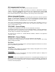
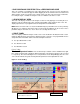
PC Communication Port Setup Plug the supplied null-modem serial cable into the PC and into the SV unit. The PC communication port settings must match the ScanVision communication parameter settings. To match the communications port baud rate to the verifier baud rate, click the Setup item on the application Menu Bar (See Figure 1). Then click the ‘Match Verifier Baudrate” menu item. ScanVision will detect the verifier’s baud rate, and set the port to the detected value.
Select Symbologies This item allows the user to program the SV unit to enable/disable individual symbology decoders. This is useful for either more secure decoding or sometimes faster throughput if a single symbology type is always being analyzed. Select Comm Port This item allows the user to select a comm port in the host PC. Change Verifier Baudrate This item allows the user to program the SV scanner/verifier baud rate.
Support Menu This menu provides special diagnostic displays and a Comm port feature that are intended to be used only while working with PTX Technical Support. About (Menu Item) This item lists information about the origin of ScanVision, the version number of this copy (it also queries the SV unit for its firmware version number) and it shows the copyright warning. SPEEDBUTTON BAR – Screen Display See Figure 1 in the Analysis Screens section. The area marked A is the Speedbutton Bar.
Report an Analysis Reports a new analysis of any bar code(s) currently in the SV unit’s beam path. This is most useful in setup where scan distance and orientation is being finalized. It is also useful when using the SV unit as a standalone verifier scanning codes being manually placed in the beam by the user. MODES OF OPERATION ScanVision operates in two basic modes: Session and Reflectance Profile. Session Mode This mode scans, analyzes and provides reports on individual bar codes.
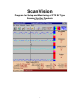
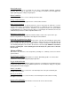
Reflectance Profile Mode This mode gathers and displays a scan reflectance profile for the entire scan path. The profile is displayed with the Reflectance Profile Screen (see Figure 3.) Reflectance Profile Mode is enabled by clicking the Reflectance Profile Speedbutton. ANALYSIS SCREENS There are two analysis screens used for setup and monitoring an SV type scanner/verifier. These are the Bar Code Analysis Screen and the Reflectance Profile Screen.
2. BAR CODE ANALYSIS RESULTS for a PREVIOUS BAR CODE This is an example of reviewing a bar code other than the last one processed as described in section 1. above. A vertical line appears while dragging the mouse with the left mouse button held down. Analysis results are shown for the column of dots (the bar code) nearest the vertical line. For example, Figure 1 exhibits the analysis results for 110th bar code in the session. 3.
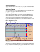
Reflectance Profile Screen This screen displays a reflectance profile for SV unit’s entire scan path. An example is shown in Figure 3 below. Figure 3 – Reflectance Profile Screen This high reflectance span includes one of the bar code quiet zones. This high reflectance span includes one of the bar code quiet zones. In this case, the bar code segment of the profile is centered in the display, therefore it is centered in the beam path.
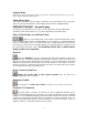
SV SCANNER/VERIFIER SETUP PROCEDURE Installation of an SV scanner/verifier requires proper mounting position, port configuration(s) and LED configurations to ensure reliable and accurate operation. This section describes the procedures for using ScanVision to ensure proper SV setup and installation. Each SV unit has a label showing the specified mounting distance and angle for its particular scanner. Follow the steps below to ensure the SV unit is properly mounted and programmed. 1. 2. 3. 4. 5. 6. 7. 8.
18. Move the code to the farthest position towards the right end of the laser beam where the code is intended to be scanned. 19. Similar to steps 15, 16 and 17, obtain an acceptable analysis and record the “Hor Pos” value for the acceptable analysis. This value will be used for the “Set Ladder Stop Position” setting later in the procedure. 20. Place the unit in Ladder mode through the Setup Menu.
SCANNER POSITIONING Each SV100 has an attached label that indicates the type of scanner, focus distance and recommended scan angle. Use the scan distance and scan angle information to mount the scanner per Figure 2. Figure 4 – Scanner Positioning Notes: 1. Scan distance is measured from the protruding edge of the face of the scanner. 2. Scan angle is measured in degrees relative to vertical from the surface of the bar code. 3.