TABLE OF CONTENTS IMPORTANT SAFETY INSTRUCTIONS 2 SAFETY PROCEDURES 3 PRECAUTIONS FOR RECEIVING AND STORING HOOD 3 WALL HOODS INSTALLATION - REMOVABLE BACK PANEL 4,5 CFM300 - 6" ROUND COLLAR 6 CFM600 - 8" ROUND COLLAR 7 CFM600 - 8" TRANSITION 8 CFM1200 - 10" TRANSITION 9 ISLAND HOODS INSTALLATION 10 DUCT COVER INSTALLATION 11 DUCT WORK INSTALLATION 12 CFM600 - 8" TRANSITION 13 CFM1200 - 10" TRANSITION 14 REMOTE FAN - ROOF OR WALL MOUNTED 15 VOLUMETRIC FLOW RATE GRAPHS 16 WIRIN
PLEASE READ COMPLETE INSTRUCTIONS BEFORE PROCEEDING. INSTALLATION MUST COMPLY WITH ALL LCOAL CODES. IMPORTANT: INSTALLER: OWNER: SAFETY WARNING: Save these instructions for the Local Electrical Inspector’s use. Please leave these instructions with this unit for the owner. Please retain these instructions for future reference. Turn power circuit OFF at the service panel and lock panel door before wiring this unit.
SAFETY PROCEDURES FOR INSTALLING YOUR NEW PRIZER HOOD (continued) CAUTION - TO REDUCE THE RISK OF FIRE, ELECTRIC SHOCK, OR INJURY TO PEOPLE, OBSERVE THE FOLLOWING: CAUTION FOR GENERAL VENTILATION USE ONLY. DO NOT USE TO EXHAUST HAZARDOUS OR EXPLOSIVE MATERIALS OR VAPORS. A. Installation work and electrical wiring must be done by a qualified installer in accordance with all applicable codes and standards, including fire rated construction. B.
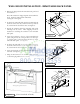
WALL HOOD INSTALLATION - REMOVABLE BACK PANEL 1. The hood is shipped with the removable back panel and the transition. Shipping Screws Removable Back Panel Note: The transition is shipped upside down within the hood. It must be removed then reinstalled. (See Figures 1 through 3) Transition Hood Assembly 2. To detach the removable back panel and transition from the hood, remove four (4) screws from the top and four (4) screws from the back of the unit. (See Figure 1) 3.
WALL HOOD INSTALLATION - (continued) 1. Attach the hood to the removable back panel by aligning the welded studs on the removable back panel with the slotted holes on the back of the hood. (See Figure 5) Soffit 2. Using the screws provided, secure the hood assembly to the removable back panel. (See Figure 5) Connector 3. Add 2”x4” wood framing block to aid in securing the top and rear of the hood to the wall. (See Figure 6) 4. To mount CFM300, CFM600 and CFM1200 fans within wall hoods.
CFM 300 IN-HOOD FAN WALL APPLICATION - 6” ROUND COLLAR COMPATIBLE WITH: - LOW PROFILE - SANTA FE 10” TALL - PRO METAL LINER 28” WIDE - METAL LINER 28” WIDE - COMPACT METAL LINER Figure 8. CFM300 Fan Volumetric Flow Rate, CFM 300 Duct Dimensions 8" dia. 250 7" dia. 200 Maximum CFM: 300 Electrical Motor Rating: 1.79 Amps @ 115V AC, 60 Hz 3 1/4" x 10" 150 6" dia. 100 50 0 0 20 40 60 80 Total Equivalent Duct Length, ft.
CFM 600 IN-HOOD FAN WALL APPLICATION - 8” ROUND COLLAR COMPATIBLE WITH: - LOW PRO-FILE - SANTA FE 10” TALL - PRO METAL LINER 28” WIDE - METAL LINER 28” WIDE - COMPACT METAL LINER Figure 9. CFM600 Fan Volumetric Flow Rate, CFM 600 Duct Dimensions 550 8" dia. 500 7" dia. Maximum CFM: 600 Electrical Motor Rating: 4.0 Amps @ 115V AC, 60 Hz 3 1/4" x 10" 450 6" dia. 400 350 300 0 20 40 60 80 Total Equivalent Duct Length, ft.
CFM 600 IN-HOOD FAN WALL APPLICATION - 8” TRANSITION EXCEPTION: - LOW PRO-FILE - SANTA FE 10” TALL - PRO METAL LINER 28” WIDE - METAL LINER 28” WIDE - COMPACT METAL LINER Figure 10. CFM600 Fan Volumetric Flow Rate, CFM 600 Duct Dimensions 550 8" dia. 500 7" dia. Maximum CFM: 600 Electrical Motor Rating: 4.0 Amps @ 115V AC, 60 Hz 3 1/4" x 10" 450 6" dia. 400 350 300 0 20 40 60 80 Total Equivalent Duct Length, ft.
CFM 1200 IN-HOOD FAN WALL APPLICATION - 10” TRANSITION EXCEPTION: - LOW PROFILE - SANTA FE 10” TALL - PRO METAL LINER 28” WIDE - METAL LINER 28” WIDE - COMPACT METAL LINER Figure 11. CFM1200 FAN Volumetric Flow Rate, CFM 1250 Duct Dimensions 1175 10" dia. 1100 9" dia. Maximum CFM: 1200 Electrical Motor Rating: 8.0 Amps @ 115V AC, 60 Hz 8" dia. 1025 950 875 800 0 20 40 60 80 Total Equivalent Duct Length, ft.
ISLAND HOOD INSTALLATION INSTALLATION ! WARNING To reduce the risk of fire, use only metal ductwork. IMPORTANT NOTE: All hoods must exhaust to the outdoors. 1. Decide the placement of the ductwork between the hood and the outside of the home. Your island hood has a top discharge which will run vertically. 2. When not installing a remote fan, always install a roof cap or wall cap. Connect 10” round metal ductwork to the roof cap and work back towards the hood location. 3.
ISLAND DUCT COVER INSTALLATION Figure 14.
ISLAND HOOD DUCT WORK INSTALLATION ! WARNING Framing must be structurally tied together and attached to the ceiling joists to provide enough strength to support the weight of the hood and the internal blower, if applicable. 1. Cut a 10” diameter opening in the ceiling to accommodate the duct work necessary for proper ventilation. 2. Transfer the overall dimensions of the hood top plate onto the finished ceiling/unfinished surface.
CFM 600 IN-HOOD FAN CHIMNEY AND ISLAND APPLICATION - 8” TRANSITION EXCEPTION: - MANHATTAN WALL 36” WIDE - MANHATTAN WALL 42“ WIDE - MANHATTAN ISLAND 36” WIDE - MANHATTAN ISLAND 42” WIDE THE ABOVE MUST BE USED WITH AN 8” ROUND COLLAR WITH BACKDRAFT DAMPER CFM600 Fan Volumetric Flow Rate, CFM 600 Duct Dimensions 550 8" dia. 500 7" dia. Maximum CFM: 600 Electrical Motor Rating: 4.0 Amps @ 115V AC, 60 Hz 3 1/4" x 10" 450 6" dia. 400 350 300 0 20 40 60 80 Total Equivalent Duct Length, ft.
CFM 1200 IN-HOOD FAN CHIMNEY AND ISLAND APPLICATION - 10” TRANSITION EXCEPTION: - MANHATTAN WALL 36” WIDE - MANHATTAN WALL 42“ WIDE - MANHATTAN ISLAND 36” WIDE - MANHATTAN ISLAND 42” WIDE THE ABOVE MUST BE USED WITH AN 8” ROUND COLLAR WITH BACKDRAFT DAMPER CFM1200 FAN Volumetric Flow Rate, CFM 1250 Duct Dimensions 1175 10" dia. 1100 9" dia. Maximum CFM: 1200 Electrical Motor Rating: 8.0 Amps @ 115V AC, 60 Hz 8" dia. 1025 950 875 800 0 20 40 60 80 Total Equivalent Duct Length, ft.
REMOTE FAN - ROOF MOUNT OR WALL MOUNT Remote Fan Round Ducting Cabinet/ Soffit Transition Remote Fan Hood Height 10” or 18” Countertop To Hood 30” - 36” Hood Depth 22”, 24” 27”, 30”, 33” Countertop To Floor 36” (standard) Figure 12.
REMOTE FANS MODEL VOLUMETRIC FLOW RATE FOR EQUIVILENT DUCT LENGTHS CFMR600 REMOTE FAN 24" 14 5/8" 5 7/8" 3 1/2" 8" Volumetric Flow Rate, CFM CFMR600 REMOTE FAN 600 Duct Dimensions 550 8" dia. 500 7" dia. 6” dia. 400 Maximum CFM: 600 Electrical Motor Rating: 4.3 Amps @ 115V AC, 60 Hz Duct Size at Discharge: 8" Square-to-round transition See ventilator & transition pages for use with hood series.
4 5 6 W G R BL BK W 4 5 6 TO LOW. SETTING TO MED.
HOOD FEATURES Model Lighting Filters WALL HOODS Halogen & Heat LP 30” - 42” Halogen 2 THIN BAFFLES LP 48” - 66” Halogen 3 THIN BAFFLES INCL 30” - 42” Halogen 2 THICK BAFFLES INCL 48” - 66” Halogen 3 THICK BAFFLES INBQ 30“ - 42” Halogen 2 THICK BAFFLES INBQ 48” - 66” Halogen 3 THICK BAFFLES BONZ 30” - 42” Halogen 2 THICK BAFFLES BONZ 48” - 66” Halogen 3 THICK BAFFLES CONN 30” - 42” Halogen 2 THICK BAFFLES CONN 48” - 66” Halogen 3 THICK BAFFLES ASPEN 30” - 42” Halogen 2 TH
BAFFLE FILTERS, GREASE TROUGHS AND LIGHTS Baffle Filters Your baffle filters come with “gripper” knobs to aid in filter placement and removal. Grab the “gripper” knobs with your thumb and index finger. Simultaneously, slide and force the first baffle filter in an upward (slightly pitched) direction towards the ceiling. (Note: spring clips have been attached within the framework to prevent the baffle filters from rattling when fan is operating.
CLEANING RECOMMENDATIONS BRUSHED STAINLESS STEEL, HAMMERED STAINLESS, EUROPEAN BLACK STEEL and MILLENNIUM DISK STAINLESS The Brushed Stainless Steel Hood should be cleaned with pre-washed flannel cloths and our recommended “Clean Source” cleaner. Always wipe in a manner which follows the grain. DO NOT clean with paper towels as they will scratch the surface. Cleaning cloths other than cotton flannel may scratch the surface of the hood.
TROUBLE-SHOOTING TIPS PROBLEM OR CONDITION POSSIBLE SOLUTION A fuse may be blown or the circuit breaker tripped. Replace the fuse or reset the breaker. Fan and Lights do not operate made incorrectly. Contact the installer. The bulb may have burned out. Fan runs but Lights do not operate The fuse for the bulb may have blown. Switch operation may be faulty. Fan does not function, but Lights operate Connect fan directly to a supply cord, by-passing hood control.