TABLE OF CONTENTS IMPORTANT SAFETY INSTRUCTIONS 2 SAFETY PROCEDURES 3 PRECAUTIONS FOR RECEIVING AND STORING HOOD 3 INSTALLATION PLANNING 4 INSTALLING CHIMNEY STYLE HOODS 5 ROUGH-IN DIMENSIONS FOR CHIMNEY STYLE HOODS 6 INSTALLING CHIMNEY STYLE HOODS (CONTINUED) 7 AN ALTERNATE INSTALLATION FOR A CHIMNEY STYLE HOOD 8 INSTALLING A CHIMNEY STYLE HOOD WITH A REAR DISCHARGE THROUGH THE DUCT COVER 9 INSTALLING A CFM600 FAN IN A 30" WIDE CHIMNEY STYLE HOOD 10 WIRING A REMOTE FAN 11 WIRING DIAG
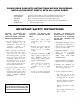
PLEASE READ COMPLETE INSTRUCTIONS BEFORE PROCEEDING. INSTALLATION MUST COMPLY WITH ALL LCOAL CODES. IMPORTANT: INSTALLER: OWNER: SAFETY WARNING: Save these instructions for the Local Electrical Inspector’s use. Please leave these instructions with this unit for the owner. Please retain these instructions for future reference. Turn power circuit OFF at the service panel and lock panel door before wiring this unit.
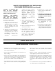
SAFETY PROCEDURES FOR INSTALLING YOUR NEW PRIZER HOOD (continued) CAUTION - TO REDUCE THE RISK OF FIRE, ELECTRIC SHOCK, OR INJURY TO PEOPLE, OBSERVE THE FOLLOWING: CAUTION FOR GENERAL VENTILATION USE ONLY. DO NOT USE TO EXHAUST HAZARDOUS OR EXPLOSIVE MATERIALS OR VAPORS. A. Installation work and electrical wiring must be done by a qualified installer in accordance with all applicable codes and standards, including fire rated construction. B.
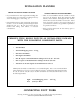
INSTALLATION PLANNING CHECK THE INSTALLATION LOCATION CHOOSE THE INSTALLATION METHOD • If your installation has been roughed-in (including duct work and wiring), be certain there is nothing in the way of the mounting, pipes, other wiring, etc. • There are several different methods available to mount the hood: the Unistrut, Angle Iron, Frame In, Wall Mounts, Island Mount and Rough-In Plate Mount, which can be used for both indoor and outdoor.
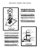
INSTALLING CHIMNEY STYLE HOODS Duct Cover use), separate the transition from the hood base and duct cover. Install the transition to the duct work ensuring the Transition transition. Verify that the transition is flush, and centered to the bottom of the Duct Cover. When transition Plate Chimney Hood Drill & Screw Into Structure is not hindered from opening if using mechanical fasteners. (see Figure 5. - Page 7) Top Electrical Knockout into the hood cavity to the electrical box. (see Figure 2.
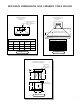
ROUGH-IN DIMENSIONS FOR CHIMNEY STYLE HOODS Electrical and Ductwork Rough-In location Top View CL Electrical and Ductwork Rough-In location Front View 10" Transition with Damper (36-66" Hood) 8" Transition with Damper (30" Hood) 6" C B Electrical Knockout Location (Rear Electrical Rough-In Location) A 18" 9-1/4" B A Electrical Knockout Location (Rear Supply) Electrical Rough-in Location (Top supply) Hood Size “A” “B” with Ductcover “C” with Ductcover “B” without Ductcover “C” without Ductcover
INSTALLING CHIMNEY STYLE HOODS - (continued) Supply Ductwork volt) (see Figure 2. - Page 4). If using a remote fan please see section “Wiring a Remote Fan”. (see Page 11) Verify that damper opens unobstructed if using mechanical fasteners that attach transition to ductwork. 10" Transition; position exhaust ductwork so bottom of transition is flush and centered with the bottom of the duct cover.
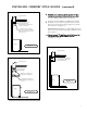
AN ALTERNATE INSTALLATION FOR A CHIMNEY STYLE HOOD In certain situations the installer may opt for a different installation sequence. The alternate sequence is listed below. Alternate Installation Supply Ductwork opening in top of structure, if available. (see Figure 7. - Page 6) Install Transition to ductwork, ensuring transition bottom Transition; Position Exhaust Ductwork so Bottom of Transition is Flush & Centered with Bottom of Duct Cover. transition to ductwork.
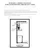
INSTALLING A CHIMNEY STYLE HOOD WITH A REAR DISCHARGE THROUGH DUCT COVER The Chimney Style Hood can adapt to a rear discharge application but with the following limitations: A rear discharge application only works when using a 24" tall duct cover or taller. The 12" and 18” tall duct covers do not allow enough room to house the transition (with damper) and an elbow. The rear discharge cannot be made within the hood itself. It can only be made in the duct cover.
INSTALLING A CFM600 FAN IN A 30” WIDE CHIMNEY STYLE HOOD These instructions are only applicable when installing a CFM600 fan in a 30" wide chimney style hood. The Prizer 30" wide chimney style hood has an adapter plate installed inside the hood. In order to install a CFM600 fan within a 30" wide chimney style hood, first remove this adapter plate, and use this plate in lieu of the plate shipped with the CFM600 fan.
WIRING A REMOTE FAN When using a remote fan with a chimney style hood, follow the instructions noted below. NOTE: The chimney style hood is designed to accept a 3-speed fan motor only. It not designed to accept a variable speed fan! 1. The molex plug mounted within the front portion of the hood supplies power to the remote fan. 2. Connect the “male” molex pigtail (included) with the remote fan to the molex plug. 3. Route the wire ends into the hood’s “J-Box”. 4.
4 TO LOW. SETTING TO MED.
CFM 600 IN-HOOD FAN CHIMNEY AND ISLAND APPLICATION - 8” TRANSITION EXCEPTION: - MANHATTAN WALL 36” WIDE - MANHATTAN WALL 42“ WIDE - MANHATTAN ISLAND 36” WIDE - MANHATTAN ISLAND 42” WIDE THE ABOVE MUST BE USED WITH AN 8” ROUND COLLAR WITH BACKDRAFT DAMPER CFM600 Fan Volumetric Flow Rate, CFM 600 Duct Dimensions 550 8" dia. 500 7" dia. Maximum CFM: 600 Electrical Motor Rating: 4.0 Amps @ 115V AC, 60 Hz 3 1/4" x 10" 450 6" dia. 400 350 300 0 20 40 60 80 Total Equivalent Duct Length, ft.
CFM 1200 IN-HOOD FAN CHIMNEY AND ISLAND APPLICATION - 10” TRANSITION EXCEPTION: - MANHATTAN WALL 36” WIDE - MANHATTAN WALL 42“ WIDE - MANHATTAN ISLAND 36” WIDE - MANHATTAN ISLAND 42” WIDE THE ABOVE MUST BE USED WITH AN 8” ROUND COLLAR WITH BACKDRAFT DAMPER CFM1200 FAN Volumetric Flow Rate, CFM 1250 Duct Dimensions 1175 10" dia. 1100 9" dia. Maximum CFM: 1200 Electrical Motor Rating: 8.0 Amps @ 115V AC, 60 Hz 8" dia. 1025 950 875 800 0 20 40 60 80 Total Equivalent Duct Length, ft.
HOOD FEATURES Model Lighting Filters WALL HOODS Halogen & Heat LP 30” - 42” Halogen 2 THIN BAFFLES LP 48” - 66” Halogen 3 THIN BAFFLES INCL 30” - 42” Halogen 2 THICK BAFFLES INCL 48” - 66” Halogen 3 THICK BAFFLES INBQ 30“ - 42” Halogen 2 THICK BAFFLES INBQ 48” - 66” Halogen 3 THICK BAFFLES BONZ 30” - 42” Halogen 2 THICK BAFFLES BONZ 48” - 66” Halogen 3 THICK BAFFLES CONN 30” - 42” Halogen 2 THICK BAFFLES CONN 48” - 66” Halogen 3 THICK BAFFLES ASPEN 30” - 42” Halogen 2 TH
BAFFLE FILTERS, GREASE TROUGHS AND LIGHTS Baffle Filters Your baffle filters come with “gripper” knobs to aid in filter placement and removal. Grab the “gripper” knobs with your thumb and index finger. Simultaneously, slide and force the first baffle filter in an upward (slightly pitched) direction towards the ceiling. (Note: spring clips have been attached within the framework to prevent the baffle filters from rattling when fan is operating.
CLEANING RECOMMENDATIONS BRUSHED STAINLESS STEEL, HAMMERED STAINLESS, EUROPEAN BLACK STEEL and MILLENNIUM DISK STAINLESS The Brushed Stainless Steel Hood should be cleaned with pre-washed flannel cloths and our recommended “Clean Source” cleaner. Always wipe in a manner which follows the grain. DO NOT clean with paper towels as they will scratch the surface. Cleaning cloths other than cotton flannel may scratch the surface of the hood.
TROUBLE-SHOOTING TIPS PROBLEM OR CONDITION POSSIBLE SOLUTION A fuse may be blown or the circuit breaker tripped. Replace the fuse or reset the breaker. Fan and Lights do not operate made incorrectly. Contact the installer. The bulb may have burned out. Fan runs but Lights do not operate The fuse for the bulb may have blown. Switch operation may be faulty. Fan does not function, but Lights operate Connect fan directly to a supply cord, by-passing hood control.