TABLE OF CONTENTS IMPORTANT SAFETY INSTRUCTIONS 2 SAFETY PROCEDURES 3 PRECAUTIONS FOR RECEIVING AND STORING HOOD 3 INSTALLATION PLANNING 4 TRANSITION INSTALLATION & REMOVAL 5 INSTALLING METAL LINERS 6 ELECTRICAL CONNECTIONS 7 CFM300 FAN - WALL APPLICATION - 6" ROUND COLLAR 8 CFM600 FAN - WALL APPLICATION - 8" ROUND COLLAR 9 CFM1200 FAN - WALL APPLICATION - 10" TRANSITION 10 COMPACT METAL LINER SLOPED SIDES (CMLSS) 11 METAL LINER SLOPED SIDES (MLSS) 12 PROFESSIONAL METAL LINER SLOPED
PLEASE READ COMPLETE INSTRUCTIONS BEFORE PROCEEDING. INSTALLATION MUST COMPLY WITH ALL LCOAL CODES. IMPORTANT: INSTALLER: OWNER: SAFETY WARNING: Save these instructions for the Local Electrical Inspector’s use. Please leave these instructions with this unit for the owner. Please retain these instructions for future reference. Turn power circuit OFF at the service panel and lock panel door before wiring this unit.
SAFETY PROCEDURES FOR INSTALLING YOUR NEW PRIZER HOOD (continued) CAUTION - TO REDUCE THE RISK OF FIRE, ELECTRIC SHOCK, OR INJURY TO PEOPLE, OBSERVE THE FOLLOWING: CAUTION FOR GENERAL VENTILATION USE ONLY. DO NOT USE TO EXHAUST HAZARDOUS OR EXPLOSIVE MATERIALS OR VAPORS. A. Installation work and electrical wiring must be done by a qualified installer in accordance with all applicable codes and standards, including fire rated construction. B.
INSTALLATION PLANNING & LAYOUT CHECK LOCATION • If your installation has been roughed-in (including ductwork and wiring), be certain there is nothing in the way of the mounting, pipes, other wiring etc. • If the installation has not been roughed in, check what is needed to create the framing and mounting hardware (allthreads, nuts, etc.). Be sure the location will not interfere with wiring, other utilities, or structural considerations.
TRANSITION INSTALLATION AND REMOVAL 1. The liner is shipped with the removable back-panel and the transition attached. 2. The transition is shipped upside-down in the liner and must be removed then, re-installed. (see Figure 1.) 3. If an in-hood fan is furnished, the transition is shipped separately. (see Figure 1. and 2.) 4. To detach the removable back-panel and the transition from the liner, remove the four (4) screws on the top and four (4) screws on the back of the liner. (see Figure 1.) 5.
INSTALLING METAL LINERS 1. If the “EZ Optional Trim Kit” will be used, it must be installed prior to mounting the metal liner to the hood shell. Use the provided #8 Phillips head screws. (see Figure 3.) 2. Lift the metal liner into the hood shell. Due to the weight of the liner, 3 or 4 men may be required to hold the liner in place to insure a tight installation. 3. Install #6 x 1/2” screws through the pre-drilled “EZ Optional Trim Kit” mount holes through to the hood shell.
ELECTRICAL CONNECTIONS 1. Install three wires: black, white and green (#16 AWG) in 1/2" conduit from the service panel to the hood junction box. Power supply must be rated for 120v, 60Hz, 15 amps (minimum). 2. Remove junction box and selected knockout. Then install the strain-relief (conduit) connector in the removable back panel. For PMLSS-28” & 34” run power line through single knockout at top and route to junction box mounted on back. 3. Remove the junction box from the removable back panel.
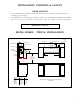
CFM 300 IN-HOOD FAN WALL APPLICATION - 6” ROUND COLLAR COMPATIBLE WITH: - LOW PROFILE - SANTA FE 10” TALL - PRO METAL LINER 28” WIDE - METAL LINER 28” WIDE - COMPACT METAL LINER CFM300 Fan Volumetric Flow Rate, CFM 300 Duct Dimensions 8" dia. 250 7" dia. 200 Maximum CFM: 300 Electrical Motor Rating: 1.79 Amps @ 115V AC, 60 Hz 3 1/4" x 10" 150 6" dia. 100 50 0 0 20 40 60 80 Total Equivalent Duct Length, ft.
CFM 600 IN-HOOD FAN WALL APPLICATION - 8” ROUND COLLAR COMPATIBLE WITH: - LOW PRO-FILE - SANTA FE 10” TALL - PRO METAL LINER 28” WIDE - METAL LINER 28” WIDE - COMPACT METAL LINER CFM600 Fan Volumetric Flow Rate, CFM 600 Duct Dimensions 550 8" dia. 500 7" dia. Maximum CFM: 600 Electrical Motor Rating: 4.0 Amps @ 115V AC, 60 Hz 3 1/4" x 10" 450 6" dia. 400 350 300 0 20 40 60 80 Total Equivalent Duct Length, ft.
CFM 1200 IN-HOOD FAN WALL APPLICATION - 10” TRANSITION COMPATIBLE WITH: - LOW PROFILE - SANTA FE 10” TALL - PRO METAL LINER 28” WIDE - METAL LINER 28” WIDE - COMPACT METAL LINER CFM1200 FAN Volumetric Flow Rate, CFM 1250 Duct Dimensions 1175 10" dia. 1100 9" dia. Maximum CFM: 1200 Electrical Motor Rating: 8.0 Amps @ 115V AC, 60 Hz 8" dia. 1025 950 875 800 0 20 40 60 80 Total Equivalent Duct Length, ft.
COMPACT METAL LINER SLOPED SIDES (CMLSS) 11
METAL LINER SLOPED SIDES (MLSS) EZ OPTIONAL TRIM KIT 12
PROFESSIONAL METAL LINER SLOPED SIDES (PMLSS) EZ OPTIONAL TRIM KIT 13
METAL LINER FLAT SIDES (MLFS) EZ OPTIONAL TRIM KIT 14
METAL LINER SLOPED SIDES ISLAND (MLSS-I) EZ OPTIONAL TRIM KIT 15
5 6 4 TO LOW. SETTING TO MED.
HOOD FEATURES Model Lighting Filters WALL HOODS Halogen & Heat LP 30” - 42” Halogen 2 THIN BAFFLES LP 48” - 66” Halogen 3 THIN BAFFLES INCL 30” - 42” Halogen 2 THICK BAFFLES INCL 48” - 66” Halogen 3 THICK BAFFLES INBQ 30“ - 42” Halogen 2 THICK BAFFLES INBQ 48” - 66” Halogen 3 THICK BAFFLES BONZ 30” - 42” Halogen 2 THICK BAFFLES BONZ 48” - 66” Halogen 3 THICK BAFFLES CONN 30” - 42” Halogen 2 THICK BAFFLES CONN 48” - 66” Halogen 3 THICK BAFFLES ASPEN 30” - 42” Halogen 2 TH
BAFFLE FILTERS, GREASE TROUGHS AND LIGHTS Baffle Filters Your baffle filters come with “gripper” knobs to aid in filter placement and removal. Grab the “gripper” knobs with your thumb and index finger. Simultaneously, slide and force the first baffle filter in an upward (slightly pitched) direction towards the ceiling. (Note: spring clips have been attached within the framework to prevent the baffle filters from rattling when fan is operating.
CLEANING RECOMMENDATIONS BRUSHED STAINLESS STEEL, HAMMERED STAINLESS, EUROPEAN BLACK STEEL and MILLENNIUM DISK STAINLESS The Brushed Stainless Steel Hood should be cleaned with pre-washed flannel cloths and our recommended “Clean Source” cleaner. Always wipe in a manner which follows the grain. DO NOT clean with paper towels as they will scratch the surface. Cleaning cloths other than cotton flannel may scratch the surface of the hood.
TROUBLE-SHOOTING TIPS PROBLEM OR CONDITION POSSIBLE SOLUTION A fuse may be blown or the circuit breaker tripped. Replace the fuse or reset the breaker. Fan and Lights do not operate made incorrectly. Contact the installer. The bulb may have burned out. Fan runs but Lights do not operate The fuse for the bulb may have blown. Switch operation may be faulty. Fan does not function, but Lights operate Connect fan directly to a supply cord, by-passing hood control.