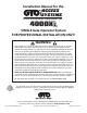
Installation Manual for the ACCESS SYSTEMS PROFESSIONAL RESIDENTIAL 4000XL SINGLE Gate Operator System FOR PROFESSIONAL INSTALLATION ONLY! WARNING! This equipment is similar to other gate or door equipment and meets or exceeds Underwriters Laboratory Standard 325 (UL 325). However, gate equipment has hazards associated with its use and therefore by installing this product the installer and user accept full responsibility for following and noting the installation and safety instructions.
Class Rating The GTO 4000XL Gate Operator is intended for use with vehicular swing gates. The operator can be used in Class I, Class II, Class III and Class IV applications. Vehicular Gate Operator Class Categories: Residential Vehicular Gate Operator—Class I: A vehicular gate operator (or system) intended for use in a home of one-to-four single family dwelling, or a garage or parking area associated therewith.
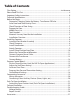
Table of Contents Class Rating.......................................................................................................................inside cover Please Read This First...........................................................................................................................ii Important Safety Instructions........................................................................................................ iii Technical Specifications........................................
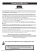
Please Read This First ® , LLC Thank you for purchasing a GTO/ACCESS SYSTEMS 4000XL. When correctly installed and properly used, your 4000XL operator will give you many years of reliable service. Please read the following information to ensure you have the correct system for your particular needs. This manual will enable you to properly install your 4000XL Automatic Gate Operator. The 4000XL operator is designed for installation on a pull-to-open single leaf gate.
IMPORTANT SAFETY INSTRUCTIONS Because automatic gate operators produce high levels of force, consumers need to know the potential hazards associated with improperly designed, installed, and maintained automated gate operator systems. Keep in mind that the gate operator is just one component of the total gate operating system. Each component must work in unison to provide the consumer with convenience, security, and safety. This manual contains various safety precautions and warnings for the consumer.
IMPORTANT SAFETY INSTRUCTIONS For The Consumer WARNING: To reduce the risk of injury or death: 1. READ AND FOLLOW ALL INSTRUCTIONS. Failure to meet the requirements set forth in the instruction manual could cause severe injury or death, for which the manufacturer cannot be held responsible. 2. When designing a system that will be entered from a highway or main thoroughfare, make sure the system is placed far enough from the road to prevent traffic congestion. 3.
IMPORTANT SAFETY INSTRUCTIONS II. During Installation 1. Install the gate operator on the inside of the property and fence line. DO NOT install an operator on the outside of the gate where the public has access to it. 2. Be careful with moving parts and avoid close proximity to areas where fingers or hands could be pinched. 3. Devices such as contact sensors (safety edges) and non contact sensors (photo beams) provide additional protection against entrapment. 4.
IMPORTANT SAFETY INSTRUCTIONS 7. To operate this equipment safely, YOU must know how to disconnect the operator for manual gate operation (page iii). If you have read the instructions and still do not understand how to disconnect the operator, contact the GTO Service Department. 8. Disconnect the operator ONLY when the power is TURNED OFF and the gate is NOT moving. 9. Make arrangements with local fire and law enforcement for emergency access. 10.
IMPORTANT SAFETY INSTRUCTIONS Secondary Means of Protection Against Entrapment As specified by Gate Operator Safety Standard, UL 325 (30A.1.1), automatic gate operators shall have an inherent entrapment sensing system, and shall have provisions for, or be supplied with, at least one independent secondary means to protect against entrapment. The 4000XL utilizes Type A, an inherent (i.e., built-in) entrapment sensing system as the primary type of entrapment protection.
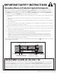
IMPORTANT SAFETY INSTRUCTIONS ! DC SW-4000XL SERIES Conforms to UL 325 STANDARDS Maximum Gate: 650 lb. (294.8 kg); 16 ft. (4.9 m) US Voltage: 12 Vdc; Frequency: 0 Hz; Power: 60 W C LIS ED T Class I, II, III and IV Vehicular Swing Gate Operator. #9901178 Serial Number: XXXXXX TO MANUALLY OPEN AND CLOSE THE GATE: 1. Turn control box power switch OFF. 2. Disconnect front or rear mount. 3. Pull operator away from front or real mounts.
Technical Specifications GTO/ACCESS SYSTEMS 4000XL AUTOMATIC GATE OPERATOR DRIVE • Low friction screw drive (linear actuator) rated for -5 ºF to +160 ºF (-21 ºC to +71 ºC). Use of heater bands on arm and control box will enhance performance in extreme cold temperatures. • Powered by a 12 V motor with integral case hardened steel gear reducer. Motor speed reduced to 300 rpm. • Maximum opening arc of 110º. Approximate opening time (90º): 18-22 seconds, depending on weight of gate.
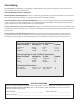
Before You Begin... 1. Determine Charging Option for Battery: Transformer OR Solar NEVER USE TRANSFORMER AND SOLAR PANEL(S) AT THE SAME TIME. It will damage the control board. IMPORTANT: • The 4000XL’s 12 volt battery must be charged by either connecting the transformer (included) or solar panel kit [FM123] to the control board. • The transformer is designed for indoor use.
2. Check Direction of Gate Swing The 4000XL is designed for PULL-TO-OPEN installations. PUSH-TO-OPEN installations require a Push-ToOpen Bracket [R4388]. Please refer to specific Push-To-Open Installation Information on page 21. Your Property Your Property Pull-To-Open (arm retracts to open) Push-To-Open (arm extends to open) 3. Prepare the Gate • • • • • The gate must be plumb, level, and swing freely on its hinges. The gate must move throughout its arc without binding or dragging on the ground.
4.
Battery (1) ! WARNING Receiver (1) GTO Transmitter(1) Moving Gate Can Cause Injury Or Death 1. KEEP CLEAR! Gate may move at any time. 2. Do not allow children to operate gate or play in gate area. 3. This gate is for vehicles only. Pedestrians must use a separate entrance. Warning Signs (4) Transformer (1) Drill Drill Bit Control Box (1) 5.
7. Installation Overview Pull-To-Open Gates (Gate Opens into the Property) The diagram shown below is an example of a Pull-To-Open installation on a chain link fence and single gate. Mounting the operator on a masonry column requires special procedures; see Column Installation Information on page 23. Furthermore, if you have a Push-To-Open gate, see Push-To-Open Installation on page 21 before proceeding.
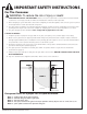
Step 1: Close the gate and place your level against the horizontal cross member. Position the level so that the top should be in the center of the cross member and overlaps the post. Scribe a line across the cross member and post. You will use this line to help determine position of post and gate brackets. Step 2: Position the post bracket on the post with the mounting holes centered over the scribe line. The post bracket should be flush with the edge of the post closest to the gate.
Step 5: 3/8” x 2-1/2” Clevis Pin Position the operator rear mount between post pivot bracket. Place a 1/2” bushing above the rear mount and a 3/16” bushing under the rear mount. Align the hole in rear mount, bushings and post pivot bracket and secure with the 2 1/2” clevis pin and hair pin clip.
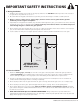
Step 8: Remove the clevis pin from the front mount and while supporting the gate Gate in the operator, swing the gate and gate 2" minimum CLOSED POSITION operator to the closed position. With Pinch Area the gate and gate operator in the closed position check the clearance and be sure that the gate operator is not binding at the post pivot bracket.
Install Closed Position Stop Plate The closed position stop plate helps to stabilize the gate leaf in the closed position. To further enhance the stability and security of your gate, install the optional GTO Automatic Gate Lock [FM144] Gate Hinge Closed Position Stop Plate Step 11 Remove hairpin, clevis pin, and 3/16” bushing from front mount and close the gate (remember to support operator).
Mount the Control Box and Receiver Step 1 or POWER INPUTS GTO SOLAR AUX AUX RLY CONTROL OUTPUTS PWR GTO LOCK LOCK PWR IN BLUE BRN ORG BLK 25 FUSE RED SLAVE INPUTS SLAVE CABLE WHT BRN BATT+ BLUE ORG RED MASTER INPUTS MASTER CABLE WHT BATT- GRN BLK COM AUTO CLOSE TIME 120 1 2 3 4 ON ON PUSH SIMULT.
Connect Operator Power Cable Space for 12 Volt battery (included). Step 1 LOCK PWR AUX AUX RLY CONTROL OUTPUTS GTO LOCK GTO TRANSF POWER INPUTS 18 VAC or SOLAR GRN PWR IN BLU BRN ORG CHARGING WHT SLAVE CABLE 25 FUSE RED BLK BATT- WHT BRN ORG RED BATT+ BLU BLK COM 120 OFF OFF AUTO CLOSE TIME OFF SOFT START OFF WARNING OFF OPEN PULL SLV OPEN DLY. ON DIP ON ON MAX STATUS S3 S2 S4 LEARN RMT LEARN SLV LIMIT ALM LEARN MAST LIMIT BLK RED ON ON PUSH SIMULT.
Connect the Transformer IMPORTANT: • The transformer is designed and intended for indoor use. If the transformer can be plugged only into an outside electrical outlet, a weatherproof cover/housing (available at local electrical supply stores) must be used. • The only wire acceptable for use with GTO products is 16 gauge multi-stranded, low voltage, direct burial wire [RB509].
Step 5 POWER INPUT AUX RLY AUX RLY CONTROL OUTPUTS PWR LOCK LOCK PWR Low Voltage Wire from AC Transformer or Solar Panel 18 VAC OR SOLAR RED BLACK ~ ~ GRN BRN ORG RED 2ND OPERATOR BLUE 2ND OPERATOR WHT BLK GRN BRN ORG RED MASTER OPERATOR BLUE BLK Power Cable from Master Arm WHT MASTER OPERATOR Strip 3/16” off the ends of the low voltage wire and twist tightly. Attach these ends to the 18 VAC OR SOLAR terminals located on the POWER INPUTS terminal block.
Step 2 IMPORTANT: Connect the BLACK battery wire to the NEGATIVE (–) battery terminal. Connect the RED battery wire to the POSITIVE (+) terminal. Reverse connection of wires will damage the control board. BLACK RED BLACK wire to NEGATIVE (–) terminal RED wire to POSITIVE (+) terminal Step 3 Plug the transformer into the electrical outlet. (Use of a surge protector with the transformer is strongly recommended.
Step 4 With the gate in the desired closed position PRESS & HOLD the “LEARN MAST LIMIT” button on the control board AUTO CLOSE TIME for 5 seconds. STALL FORCE STATUS Step 5 LEARN RMT MIN MAX ON DIP 1 2 3 4 Press the transmitter button and 120 allow the gate to return to the fully open position (arm fully retracted). SOFT START OFF The gate closed position limit is now WARNING OFF OPEN PULL programmed. SLV OPEN DLY.
Set Auto Close Time AUTO CLOSE TIME STALL FORCE STATUS LEARN RMT 120 OFF OFF OFF PULL DLY. MODE1 MODE2 Auto Close Time Potentiometer MAX S3 ON ON PUSH SIMULT. ON DIP SOFT START WARNING OPEN 2ND OPEN MIN 1 2 3 4 The Auto-Close Time potentiometer controls the Auto-Close feature, and determines how long the gate will remain open (at the fully open position) before it begins to close. The settings for this feature are OFF, or from 3 to 120 seconds.
Control Board Settings DIP Switches ON DIP ON OFF AUTO CLOSE TIME STALL FORCE STATUS LEARN RMT OFF OFF OFF PULL DLY. OFF OFF MIN MAX ON DIP SOFT START WARNING OPEN 2ND OPEN MODE1 MODE2 120 1 2 3 4 18 GTO 4000XL Instruction Manual © 091610 1 2 3 4 Main DIP Switch Settings (MODES) DIP Switch #1: Soft Start/Stop ON– Soft start enabled (factory preset). OFF– Soft start disabled.
Connnecting Accessories Input Connections • All control inputs are dry-contact, normally open, inputs. DO NOT apply external voltage sources to these inputs. • All inputs are connected with respect to COMMON terminal. • The status LED will blink once when its corresponding input is activated. COM 1 COM: Circuit common (reference for all logic input) • Two (2) terminals to provide extra common connection point.
Wiring Accesories AUX RLY LUE GRN BRN W ORG RED BLK COM STER INPUTS 1 COM 2 3 4 5 6 OPEN EDGE LOCK PWR or SOLAR CLOSE EDGE 18 VAC CONTROL INPUTS STER CABLE EXIT OPEN AUX RLY SHADOW LOOP PWR SAFETY LOCK CYCLE CLOSE TRANSF GRN 7 6 7 Automatic Gate Lock BLK RED RECEIVER ALM According to Application 1 Edge Sensor 3 4 5 ON DIP NO COM NC V+ V– LOOP LOOP 1 2 3 4 5 6 7 8 9 10 1 According to Application Loop Detector 3 1 Photo Beams LOOP 1 2 Push Button Control 4 1
Push-To-Open Installation Information Swinging gates shall not open into public access areas! A “Push-to-Open” gate opens out from the property (operator arm extends to open the gate). A Push-ToOpen installation requires the purchase of a Push-To-Open Bracket [R4388]. In a Push-To-Open installation the operator is installed while the gate is in the CLOSED POSITION. Install the Operator Follow directions for installing the 4000XL beginning on page 7.
2 3 4 OFF ON ON MAX OFF OFF MIN 120 OFF OFF PULL DLY. DLY. 1 2 3 4 MODE1 MODE2 1 ON DIP OFF ON AUTO CLOSE TIME ON SOFT START WARNING OPEN SLV 2ND OPEN OPEN STALL FORCE Make sure the control box power switch is OFF. Use a small screwdriver to move the Number 3 DIP switch from the factory setting (OFF / Pull-To-Open) to ON for Push-To-Open. Turn power switch ON. The control board is now configured to push the gate open. ON ON PUSH SIMULT.
Column Installation If this operator will be used with gates that are mounted on masonry, brick, or rock (etc.) columns, read the following carefully before proceeding A. The simplest solution is to install the operator in a push-to-open configuration. The minimum clearance is easier to achieve and clearance is no longer a problem, since the operator will be pushing the gate away from the column instead of pulling it toward the column.
Troubleshooting Guide If your gate operator does not function properly after it is installed, use this guide before calling the GTO Service Department.
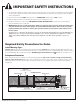
Generation 3 Visual Feedback SYMPTOM DIAGNOSIS Status (clear)1 blink Cycle Terminal Shorted CHECK: • Disconnect the push button, keypad, intercom keypad, or any other accessory wired to this terminal. • Try the remote. If the remote works, then the problem is the accessory. Status (clear) 2 blinks Safety Terminal Shorted • Disconnect the loop detector, photo beam, or any other accessory wired to this terminal. • Try the remote. If the remote works, the problem is the accessory.
Repair Service If your GTO 4000XL Gate Operator is not operating properly, please follow the steps below: 1. First use the procedures found in the Troubleshooting Guide (see page 24). 2. Use the 24/7 Troubleshooting Wizard at http://support.gtoinc.com. 3. If you are unable to solve the problem, call the GTO Service Department at (800) 543-1236, or (850) 575-4144. Refer to the serial number (located on the right side of the control box) and date of purchase when calling for assistance. 4.
Accessories for 4000XL Please visit www.gtoaccess.com for photos and detailed descriptions of GTO Accessories. Or call 1-800-543-GATE (4283). POWERING ACCESSORIES Low Voltage Wire [RB509] The 16 gauge, multi-stranded, dual conductor low voltage Wire is for connecting the AC powered transformer, solar panel or wired accessories to the system’s control board. This specially designed wire is UV treated, PVC coated, and ready for direct burial.
Ans wer Per Grant mis sio n Ke Ba ypa tt d Low POW ER Residential Wireless Entry Intercom [F3100MBC] Designed for added security to your automated gate with the ability to “speak to” and “screen” visitors safely from inside your home. Ideal for securing gate entrances while providing controlled access. DV 9V Gooseneck Pedestal [F100/F110] Designed to mount digital keypads, wireless intercom systems, and other access control devices for your gate automation system.
ADDITIONAL Accessories Photo Beams [R4222] Primary “through beam” photo beam device. Provides “non-contact” entrapment protection. Pin Lock [FM345] Use as a substitute for the clevis pin at the front mount of the PRO-SW4000XL to prevent theft of the operator. • Pin Lock 10-pack: ten Pin Locks keyed alike [FM345KA]. Push Button Control [RB10] Wire this unlit push button directly to your gate operator for simple open/close/stop operation from up to 1000 ft. away. Use 16 gauge low-voltage wire.
ACCESS SYSTEMS PROFESSIONAL RESIDENTIAL 3121 Hartsfield Road • Tallahassee, Florida, USA 32303 (850) 575-0176 • Fax (850) 575-8912 Web site www.gtoaccess.com 24/7 Troubleshooting Wizard: http://support.gtoinc.