
Owners manual


13134
Revised
11.30.05
4
INSTALLATION INSTRUCTIONS:
NOTE: In order to properly install the add-a-leaf spring, it will be necessary to
contain the elasticity in the leaf spring with “C” clamps when the center bolts are re-
moved. Some springs have a factory helper spring consisting of one or more flat
leaves installed at the bottom of the leaf pack. DO NOT install the add-a-leaf spring
in or below the helper spring.
1) Measure the vehicle from the center of the hub to the fender lip and record this meas-
urement below.
2) Block the front tires and raise the rear of the vehicle. Support the frame with jack
stands forward of the rear springs.
3) Remove the rear wheels.
4) Unbolt the shocks at the lower shock mount on both sides of the vehicle. It may be
necessary that you slightly raise the axle to unload the shocks for removal.
5) Support the rear axle with a floor jack and remove the U-bolts on the driver side.
Loosen the U-bolts on the passenger side.
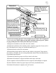
8) Hold the spring assembly securely together with “C” clamp. Spread apart spring leaf
alignment clamps. Remove the spring center bolts. A hammer and drift punch may be
used to drive them out if necessary.
9) Carefully remove “C” clamp. Lower axle, disassemble leaf spring and insert add-a-
leaf (13134).
NOTE: Add-a-leaf will be placed in the spring assembly progressively accord-
ing to length. For example, if the existing leaves are 32” long and 25” long and the
add-a-leaf is 28” long, place the add-a-leaf between the existing leaves.
10) Re-clamp and bolt the leaf pack back together using the supplied center bolts (97-
120) with the heads of the bolts facing down and the nut on the top. When you are fin-
ished you may need to trim the excess thread from the center bolts, so that it does not hit
the U-bolt bracket on top of the leaf springs. Bend the alignment clamps back around
the leaves.
11) Make sure the pins fit into the holes on the spring perch. Use your floor jack to raise
the axle to the spring making sure the heads on the factory leaf fit into the holes on the
lift block.
LR: RR:
LF: RF: