2360 Boswell Road Chula Vista, CA 91914 Phone 619.216.1444 Fax 619.216.1474 E-Mail tech@explorerprocomp.com PRO COMP SUSPENSION Suspension Systems that Work! PN# 55506 96-06 Jeep TJ Sway Bar Quick Disconnect Kit To Be Used in Conjunction With 3”- 5” Lift Kits This document contains very important information that includes warranty information and instructions for resolving problems you may encounter. Please keep it in the vehicle as a permanent record.
Revised: 5/14/07 BILL OF MATERIALS: Part # Description 90-1092 ADAPTER MOUNT 2 2,3 4,5 90-6024 37C150HCS5Z 37C250HCS5Z 37CNNE5Z 37NWSAZ 37NWUS8Y HARDWARE PACK: End Links 3/8-16 X 1 1/2 HEX CAP SCREW GR 5 ZINC 3/8-16 X 2 1/2 HEX CAP SCREW GR 5 ZINC 3/8-16 NYLON INSERT L/N GR 5 ZINC 3/8 SAE FLAT WASHER ZINC 3/8 USS FLAT WASHER GR 8 ZINC/YELLOW 1 2 2 4 4 2 3 2 2,3 2,3 2,3 5 4 4,5 4,5 4,5 90-6046 45359 61150 60859H 600001 HARDWARE PACK: Bushings and Sleeves 5/8" BLACK HOURGLASS BUSHING SLEEVE 5/8
Introduction: ♦ This installation requires a professional mechanic! ♦ We recommend that you have access to a factory service manual for your vehicle to assist in the disassembly and reassembly of your vehicle. It contains a wealth of detailed information. ♦ Prior to installation, carefully inspect the vehicle’s steering and driveline systems paying close attention to the tie rod ends, ball joints, wheel bearing preload, pitman and idler arm.
INSTALLATION INSTRUCTIONS: FRONT SWAY BAR: 1. Position your vehicle on a smooth, flat, hard surface (i.e. concrete or asphalt). Block the rear tires and set the emergency brake. 2. Place the vehicle in neutral. Place your floor jack under the front axle and raise the front of the vehicle. Place jack stands under the frame rails to support the vehicle. 3. Unbolt and remove factory sway bar end links. 4.
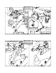
Adapter 90-1092 Illustration 3 3/8” x 2 1/2” Bolt Sway Bar and pin Install Lower Locking Pin 90170A212 Sway Bar End Link 90-2638 Sway Bar End Link 90-2638 Finished Lower Mount 1/2” Hardware Sway Bar Clamp 90-3579 Illustration 4 Sway Bar Disconnected Lower Locking Pin 90170A212 Sway Bar End Link Quick Disconnect Pin 90-2593 Lower Axle Mount
with the locking pin 90170A212 and 5/8” washer. See ILLUSTRATION 3. 12. Repeat on the remaining side of the vehicle. 13. Temporarily install the front wheels and turn lock to lock to check for interference. When Disconnected: 14. When disconnecting the sway bar links, swing the end links up into the previously installed clamp on the sway bar above. Secure the sway bar end link (90-2638) into the clamp (90-3579) using the previously removed locking pin 90170A212. See ILLUSTRATION 4. 15.
Bolt Torque and ID Decimal System Bolt Size 5/16 3/8 7/16 1/2 9/16 5/8 3/4 Metric System All Torques in Ft. Lbs. Grade 5 Grade8 Bolt Size Class 9.8 Class 10.9 Class 12.9 15 20 M6 5 9 12 30 45 M8 18 23 27 45 60 M10 32 45 50 65 90 M12 55 75 90 95 130 M14 85 120 145 135 175 M16 130 165 210 185 280 M18 170 240 290 T T D D L 1/2-13x1.75 HHCS D T L L G X Grade 5 Grade 8 (No.
Notice to Owner operator, Dealer and Installer: Vehicles that have been enhanced for off-road performance often have unique handling characteristics due to the higher center of gravity and larger tires. This vehicle may handle, react and stop differently than many passenger cars or unmodified vehicles, both on and off–road. You must drive your vehicle safely! Extreme care should always be taken to prevent vehicle rollover or loss of control, which can result in serious injury or even death.