52612 Revised 8.21.07 2360 Boswell Road Chula Vista, CA 91914 Phone 619.216.1444 Fax 619.216.1474 E-Mail tech@explorerprocomp.com PRO COMP SUSPENSION Suspension Systems that Work! Part # 52612 (formerly 52602) 99-2004 Super Duty 2WD F250-350 This document contains very important information that includes warranty information and instructions for resolving problems you may encounter. Please keep it in the vehicle as a permanent record.
52612 Revised 8.21.07 * * INSTALLATION REQUIRES A NEW PITMAN ARM. PRODUCTION DATE PRIOR TO APRIL 1ST, 1999 USE PART# FD400. AFTER APRIL 1ST, 1999 USE PART# FD600. * * PARTS LIST: BOX 1 OF 4 ITEM# DESCRIPTION QTY. ILLUST.
52612 Revised 8.21.07 ITEM# DESCRIPTION QTY. ILLUST. BOX 2 OF 4 95-150F 90-1859 1-1/2” Aluminum Block Sway Bar Drop 2 2 90-2144 13-90256 20-65471 BOX 3 OF 4 Bump stop Spacers 5/8” x 3.3” x 12.6” U-Bolt Hardware Packet - 5/8” Nut & Washers 2 4 1 97-716 8771-1 13128-1 7/16” x 4” Center Bolt 7/16” Nut fine Gr.
52612 Revised 8.21.07 Introduction: ♦ This installation requires a professional mechanic! ♦ We recommend that you have access to a Ford service manual for your vehicle to assist in the disassembly and reassembly of your vehicle. It contains a wealth of detailed information. ♦ Prior to installation, carefully inspect the vehicle’s steering and driveline systems paying close attention to the tie rod ends, ball joints and wheel bearing preload.
2612 Revised 8.21.07 2)Measure and record the distance from the center of each wheel to the top of its fender opening. Record below. LF: RF LR: RR: 3) Raise the front of the vehicle with a floor jack and support with jack stands behind the radius arm mounts. (Never work on a vehicle while it is on the floor jack and unsupported by jack stands). 4) Remove front tires. Remove sway bar links at the sway bar. Retain all hardware (It will be reused).
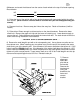
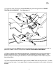
52612 Revised 8.21.07 8) Install 90-1241 radius arm bracket and spacer using the factory hardware. (See Illustration 1) Torque mounting hardware to 65 ft. lbs. 9) Install radius arm into bracket and install pivot bolt. It will be necessary to raise the I-Beam to align the bolt holes in the bracket with the radius arm sleeve. DO NOT TIGHTEN PIVOT BOLT AT THIS TIME. * * REPEAT STEPS 7 - 9 ON DRIVER SIDE * * 10) Remove I-Beam pivot bolts on both sides.
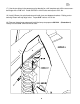
52612 Revised 8.21.07 13) Install the driver I-Beam pivot bracket 90-1245 using the existing hardware. DO NOT TIGHTEN ANY HARDWARE. (See Illustration 3) 14) Install the pivot strut 90-2120 between the passenger and driver pivot brackets and hold it in place with the 9/16” x 3-1/2” bolts provided. DO NOT TIGHTEN ANY HARDWARE. 15) Begin to tighten I-Beam pivot bracket hardware. Rotate back and forth from one bracket to the other one bolt at a time.
52612 Revised 8.21.07 17) Use the two holes in the passenger pivot bracket for a drill template and drill the cross member flange with a 7/16” drill. Install the 7/16” x 1-1/4” bolts and torque to 50 ft. lbs. 18) Install I-Beams into pivot brackets and install pivot strut between brackets. Raising and or lowering I-Beam will help align holes. Torque 9/16” bolts to 105 ft. lbs. 19) Remove factory bump stops and install the bump stop spacers 90-2144.
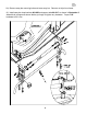
52612 Revised 8.21.07 20) Remove sway bar mounting bolts and lower sway bar. Remove nut clips from frame. 21) Install sway bar drop brackets 90-1859 and support tube 90-2117 as shown in Illustration 5. Assemble all components shown before you begin to tighten any hardware. Torque 7/16” hardware to 50 ft. lbs.
52612 Revised 8.21.07 22) Raise driver I-Beam and remove shock absorber. 23) Lower I-Beam and install new coil. Raise I-Beam until it begins to compress coil and install the coil retaining hardware top and bottom. 24) Install new front shock 921510 and tighten hardware. * * REPEAT STEPS 22 - 24 ON OPPOSITE SIDE * * 25) If installing optional cam kit (594) remove pinch bolt. Remove cam from driver side I-beam and slide in new eccentric cam. Replace pinch bolt. Do not tighten at this time.
52612 Revised 8.21.07 27) Replace front tires and set vehicle on ground. Connect sway bar links to sway bar and torque to 55 ft. lbs. Torque radius arm bolts to 105 ft. lbs. 28) Cycle steering full right to full left, checking for any steering linkage contact or brake line contact. Front brake lines should be of adequate length. However, the steel portion may need to be bent slightly to clear the larger tire. REAR INSTALLATION: 1) Block both front wheels in front and behind tires.
52612 Revised 8.21.07 11) Raise axle until the vehicle begins to lift off the jack stands. Torque U-bolts to 115 ft. lbs. 12) Install 929508 rear shock. 13) Install tires and lower vehicle to ground. CHECKS AND ADJUSTMENTS: Have front end aligned. Have head lights adjusted. Re-torque all hardware after first 100 miles.
52612 Revised 8.21.
52612 Revised 8.21.07 Notice to Owner operator, Dealer and Installer: Vehicles that have been enhanced for off-road performance often have unique handling characteristics due to the higher center of gravity and larger tires. This vehicle may handle, react and stop differently than many passenger cars or unmodified vehicles, both on and off–road.