
Owners manual


52612
Revised
8.21.07
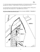
22) Raise driver I-Beam and remove shock absorber.
23) Lower I-Beam and install new coil. Raise I-Beam until it begins to compress coil and install
the coil retaining hardware top and bottom.
24) Install new front shock 921510 and tighten hardware.
* * REPEAT STEPS 22 - 24 ON OPPOSITE SIDE * *
10
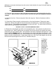
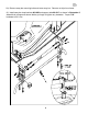
25) If installing optional cam kit (594) remove pinch bolt. Remove cam from driver side I-beam
and slide in new eccentric cam. Replace pinch bolt. Do not tighten at this time. Repeat on re-
maining side of vehicle. Turn the wheel full lock to the left and grind the visible backs of the spin-
dles around the ball joint removing approximately 3/16”. Start at the top, tapering down to nothing
at the bottom. Turn wheel to full lock the opposite way and grind the remaining, now visible, spin-
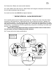
dle area. (See Illustration 6)
NOTE: After grinding adjust each side to maximum camber and turn wheel lock to
lock and make sure there is adequate spindle clearance.
26) Torque pinch bolt to factory specifications.
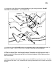
Clearance:
Top View
Illustration 6
Optional Cam
Clearance 3/16”
Clearance:
front View
Clearance:
Rear View