
Owners manual
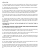
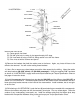
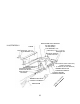
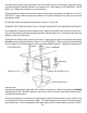
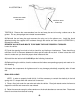

ILLUSTRATION 6
DRIVER SIDE SWAY
BAR MOUNT
REMOVE USING
TEMPLATE
TRATION 6. Remove the crossmembers from the anti-sway bar and trim using a saber saw or die
grinder. File any sharp edges and reinstall crossmembers.
26) Reinstall the anti-sway bar and reconnect the relay rod to the pitman arm. Install the shock
absorbers using the supplied 1/2” hardware through the radius arm hole (see ILLUSTRATION 1).
Reinstall the wheels.
RECHECK ALL NUTS AND BOLTS TO BE SURE THEY ARE PROPERLY TORQUED.
Lower the vehicle.
27) Cycle the steering from lock to lock to check for any binding or interference. There should be a
minimum of 1.0” of clearance between the tires and the radius arm at lock. If there is less then 1.0”
check to make sure you have the proper wheel offset and size.
28) Install the dual add-a-leaf kit #13130 per the following instructions.
29) Before driving the vehicle, check to make sure the brakes are operating properly and need no fur-
ther bleeding.
30) Inspect the components for tightness and for any damage periodically, especially after off-road
use.
DUAL ADD-A-LEAF:
NOTE: In order to properly install this kit, it will be necessary to contain the elasticity in the leaf
spring with “C” clamps when the center bolt is removed.
1) Place a floor jack under the rear axle and raise the vehicle. Place jack stands under the frame to
support the vehicle and remove the rear wheels.
2) Raise the rear axle enough to relieve tension on the shock absorbers an remove them. Disconnect
the axle vent hose from the axle housing.
10