
Owners manual
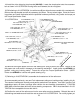

Remove the rivets as follows:
A) Center punch rivet head
B) Drill 1/4” pilot hole in center of rivet approximately 1/4” deep
C) Drill rivet head off using a 7/16” bit, being careful not to drill into frame.
D) Drive rivet out with a hammer and punch.
10) Remove the brackets that held the radius arms to the frame. Again, any rivets will have to be
drilled to be removed. You will not be reusing these brackets.
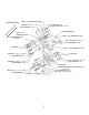
11) Use a file to remove any raised edges around the hole caused by the drilling. Mount the radius
arm drop brackets (90-1005, driver) and (90-1006, passenger). Using the supplied 7/16” hardware
as shown in ILLUSTRATION 2, apply loctite and torque fasteners per Torque Specification Chart on
last page of instruction sheet.
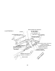
12) Install the passenger side I-beam pivot drop bracket (90-1202) and the stiffener plate (90-1197) as
shown in ILLUSTRATION 3. The stiffener plate mounts on the outside of the crossmember and the I-
beam pivot drop bracket mounts on the inside of the crossmember. Install hardware, but do not tight-
en at this time.
13) Still referring to ILLUSTRATION 3, mark the four (4) new holes that are needed with a centerpunch.
Remove the bracket and plate and drill the necessary size holes. File any raised edges. Clean the
surface of any undercoating, loose paint, etc. Install the stiffener plate and the I-beam pivot drop
bracket with the specified hardware using loctite and torque per Torque Specification Chart.
5
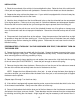
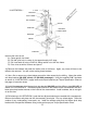
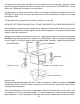
ILLUSTRATION 1
“J” CLIP
EXISTING
COIL TOWER
COIL SPRING
EXISTING
EXISTING
I-BEAM
EXISTING
SHOCK
EXISTING
RADIUS ARM
EXISTING
FRONT OF VEHICLE