
Owners manual

the other side.
24) Install the appropriate length brake lines. Refer to the parts list. (Brake line support kit (90-6029)
included with this kit). Bleed the brakes to remove any air from the lines according to factory recom-
mendations and instructions.
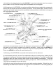
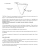
25) If the anti-sway bar is mounted to a crossmember instead of the frame rails on your vehicle, it will
be necessary to trim the crossmember slightly. Full scale templates are included on the last page of
these instructions. Cut the templates out and trace them onto the crossmember as shown in ILLUS
9
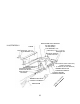
19) Using the floor jack, raise and position one of the beams into the new bracket. Insert the existing
pivot bolt through the bracket and beam and install the nut. Refer back to ILLUSTRATION 3. Do not
tighten yet. Repeat this procedure on the other beam.
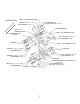
20) Check again, to make sure that all the radius arm bushings and spacers are installed as in ILLUS-
TRATION 2. Apply loctite and torque the radius arm nuts and the beam pivot bolts per the Torque
Specification Chart.
21) Reinstall the front driveshaft and torque the u-bolts to 12-15 ft./lbs.
RECHECK THE TORQUE VALUES OF ALL THE NUTS AND BOLTS THAT HAVE BEEN INSTALLED.
22) If applicable, reinstall the power steering cooler. Make sure that the cooler lines do not rub or con-
tact any metal surfaces that may damage them (bolts, bracket edges, etc.) If necessary, bend the lines
slightly to clear any obstructions.
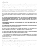
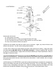
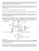
23) Remove the factory bump stop from the frame. Install the bump stop onto the bump stop spacer
(91-2144) using existing hardware as shown in ILLUSTRATION 5. Mount the bump stop assembly
onto the frame in the original location using the supplied 5/16” hardware. Repeat this procedure on
ILLUSTRATION 5
FRAME
5/16” HARDWARE
EXISTING
BUMP STOP SPACER 91-2144
FACTORY BUMP STOP
HEX BOLT, 5/16” X 1”