2360 Boswell Road Chula Vista, CA 91914 Phone 619.216.1444 Fax 619.216.1474 E-Mail tech@explorerprocomp.com PRO COMP SUSPENSION Suspension Systems that Work! Part # 57095 Toyota Tacoma 4WD IFS 4” Suspension System This document contains very important information that includes warranty information and instructions for resolving problems you may encounter. Please keep it in the vehicle as a permanent record.
57095 Revised 2.28.2008 Box 1 of 2 PN 57095-1 PART# DESCRIPTION QUANTITY ILLUSTRATION# NOTE: This instruction packet contains valuable warranty information and should be kept in the vehicle as a permanent record. NOTE: Part #7213 extended brake lines are required to complete the installation of the 57095 kit and must be purchased separately. NOTE: An instructional video is available for this suspension system. Contact Pro Comp customer service to obtain the video.
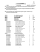
57095 Revised 2.28.2008 90-6146 020100 90-1083 90-1336 90-1339 90-1340 90-1344 90-1345 90-1347 90-2075 90-2166 90-2169 90-6144 70-0311751500 73-03100030 72-03100100512 90-6140 90-4029 90-4030 90-6145 73-06200032 90-2167 90-6143 70-0502252800 73-05000538 72-05000200816 90-6139 13-22106 13-10016-B 13-30434-Z 13-10566-Z Loctite Tube - Small, Red Bracket Bag Containing: U-Bolt ABS Wiring Extension Steering Box Support Bracket Sway Bar Drop Bracket (pass.
57095 Revised 2.28.2008 The following special tools will be required for the proper installation of this kit. NOTE: The following parts are used in conjunction with this kit and must be ordered separately. TOYOTA #09610-20012 BALL JOINT PULLER TOYOTA #09628-62011 TIE ROD PULLER BALL JOINT TOOL (SUPPLIED WITH KIT) ALLEN SOCKET, 12MM HOIST STANDS (2 REQUIRED) ITEM# DESCRIPTION QTY.
7095 Revised 2.28.2008 PRIOR TO INSTALLATION: • Installation by a professional mechanic is recommended. Use of the appropriate power tools, a Toyota Tacoma service manual and a shop hoist can greatly reduce installation time. • Check the production date of your vehicle. Vehicles manufactured prior to 10/95 may require additional parts to complete installation. If the front end alignment cams measure 1.
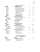
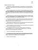
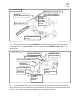
57095 Revised 2.28.2008 Front Installation: ILLUSTRATION 1 ILLUSTRATION 2 1) Remove grease cap, cotter pin and locking cap (ILLUSTRATION 1). While applying brakes, loosen axle nuts with a 35mm socket. Do not remove at this time. 2) Block rear wheels, set parking brake, raise front of vehicle and support with jack stands. Do not work on any vehicle unsupported by jackstands. Remove front wheels, tires and O.E.M. skid plates. 3) Place a jack under front lower a-arm. Remove lower nut from front shock mount.
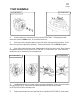
57095 Revised 2.28.2008 ILLUSTRATION 5 ILLUSTRATION 6 the two (2) bolts that attach brake caliper to front spindle. Support the brake caliper securely so it cannot swing freely. ILLUSTRATION 7 ILLUSTRATION 8 BALL JOINT PULLER 09628-62011 TIE ROD PULLER 09610-20012 6) Remove rotor (ILLUSTRATION 6) by using a snap ring expander and removing the snap ring. (Some models may not have snap rings). 7) Using a strap, support the front drive axle from resting at full bind.
57095 Revised 2.28.2008 #09610-20012 (ILLUSTRATION 8), disconnect tie rod ends. ILLUSTRATION 9 9) Locate the four (4) bolts attaching the lower ball joint on the a-arm to the front spindle (ILLUSTRATION 9). Remove the four bolts, axle nut and spindle 10) Locate the power steering unit. Disconnect the pressure feed and return lines at control valve housing. Make sure that you have a pan to catch the power steering fluid as you disconnect these lines. Remove steering unit from chassis.
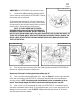
57095 Revised 2.28.2008 ILLUSTRATION 12 CUT LINES ARE 2 1/4” FROM CENTER LINES 2 1/4” EXISTING REAR CROSSMEMBER SKIDPLATE TABS See note 13 CUT LINE FRAME 2 1/4 MAX CUT HERE ORIGINAL A-ARM LOCATION MAKE SURE NOT TO DAMAGE OR CUT A-ARM BOOT POWER STEERING UNIT MOUNT After cutting the crossmember, it is very important that the remaining material on the drivers side rear area be completely removed to clear the power steering adapter tube.
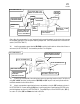
57095 Revised 2.28.2008 ILLUSTRATION 15 HEX BOLT, 3/4” X 4 1/4” LG. EXISTING REAR CROSSMEMBER LOCATING WASHERS CROSSMEMBER SUPPORT BRACKET, 90-1344 TOP LOCK NUT, 3/4” T ON R F C HI E V OF LE REAR CROSSMEMBER, 90-1354 17) Next, position front crossmember (90-1332) into existing lower front a-arm mounting locations (ILLUSTRATION 17) using 3/4” x 4 1/4” hex bolts, locating washers (90-1345) and 3/4” top lock nuts; fasten loosely.
57095 Revised 2.28.2008 ILLUSTRATION 17 EXISTING FRONT CROSSMEMBER WASHER, LOCATING 90-1345 HEX BOLT, 3/4” X 4 1/4” LG WASHER, LOCATING 90-1345 TOP LOCK NUT, 3/4”-10 FRONT CROSSMEMBER 90-1332 NT O FR OF ILLUSTRATION 18 E ILLUSTRATION 18a FLAT WASHER, 1/2” DIFFERENTIAL MOUNT SPACER, 90-2166 VE CL HI PN 90-2075 TOP LOCK NUT, 1/2” EXISTING FRONT CROSSMEMBER FRONT DIFFERENTIAL See instruction 19 ILLUSTRATION 18b FRONT CROSSMEMBER, 90-1332 FLAT WASHER, 1/2” HEX BOLT, 1/2” X 11” LG.
57095 Revised 2.28.2008 NOTE: There are currently two crossmembers being shipped. One has spacers welded as indicated in ILLUSTRATION 18b, one does not, ILLUSTRATION 18a. If you have a crossmember with the spacers welded in place, DO NOT use spacer (90-2075). If you DO NOT have the spacers welded in place, you must use these spacers as indicated. ILLUSTRATION 19 FRONT DIFFERENTIAL NYLOC NUT, 3/8” 19) Using the differential mounting spacers REAR (90-2166), hex bolts 1/2” x 11” Lg.
57095 Revised 2.28.2008 hose. Attach return line to existing location on vehicle using hose clamp at the end of the return line (Refer back to ILLUSTRATION 23). Tighten both return and pressure lines at control valve housing. Reconnect tie-rod ends to lower steering arm. (A new cotter pin should be used) Torque nut to 41 ft./lbs. Tighten all hardware. See torque specifications chart on the last page. 25) Next, press ball joint out of the front spindle using the ball joint puller.
57095 Revised 2.28.2008 ILLUSTRATION 24 FLAT WASHER, 5/8” NYLOC NUT, 5/8” NYLOC NUT,9/16” FLAT WASHER, 9/16” HEX BOLT, 5/8” X 2 3/4” LG. STEERING BOX SUPPORT BRACKET 90-1336 FLAT WASHER, 5/8” POWER STEERING UNIT EXISTING REAR CROSSMEMBER SPLIT LOCK WASHER, 9/16” FLAT WASHER, 5/8” REAR CROSSMEMBER 90-4013 FLAT WASHER, 5/8” FLAT WASHER, 9/16” NYLOC NUT, 5/8” HEX BOLT, 5/8” X 8 1/2” LG. HEX BOLT, M14 X 90MM LG. ILLUSTRATION 24A HEX BOLT, 9/16” X 8 1/2” LG.
57095 Revised 2.28.2008 ILLUSTRATION 25 EXISTING HEX BOLT, 1/2” X 2 1/4” LG. T ON R F FLAT WASHER 1/2” A.N. OF LE IC H VE SPINDLE SPACER, 90-4013 U-BOLTS IN PART PACK 020100 FLAT WASHER, 5/16” A.N. SET SCREW, 3/8” X 1 1/2” FLAT WASHER, 1/2” A.N. TOP LOCK NUT, 5/16” TOP LOCK NUT, 1/2” JAM NUT, 3/8” SPINDLE SUPPORT BRACKET, 90-1328 (PASS.) 90-1329 (DRVR.)SHOWN FRONT HUB ASSEMBLY the 1/2” nut attaching spindle spacer to spindle to 90 ft./lbs. and the steering arm nut to 83 ft./lbs.
57095 Revised 2.28.2008 ILLUSTRATION 26 60 ft./lbs. NYLOC NUT, 7/16” 31) Install sway bar drop brackets (90-1339, Pass./90-1340, Drvr.) to existing sway bar upper mounting locations using existing hardware. (ILLUSTRATION 27). Torque hardware to 19 ft./lbs. FLAT WASHER, 7/16” 32) Install sway bar to sway bar mounting brackets with spacer (90-1508) installed as illustrated, using the 5/16” hardware provided. Do not tighten. Locate lower sway bar mount on lower a-arm.
57095 Revised 2.28.2008 ILLUSTRATION 28 FRONT CROSSMEMBER 90-1332 REAR CROSSMEMBER 90-1354 SKIDPLATE 90-1369 FLAT WASHER, 3/8” HEX BOLT, 3/8” X 1” LG. ILLUSTRATION 29 LOAD SENSING PROPORTIONING VALVE FLAT WASHER, 5/16” FLAT WASHER, 5/16” HEX BOLT, 5/16” X 1 3/4” LG.
57095 Revised 2.28.2008 ILLUSTRATION 30 ILLUSTRATION 31 Configuration of emergency brake cable after modification Original configuration of emergency brake cable 41) Disconnect the emergency brake cables from the brake drum backing plates. (Both sides). 42) On the driver side of the vehicle at the rear of the gas tank, remove the emergency brake cable bracket from the gas tank clamp. See ILLUSTRATION 30.
57095 Revised 2.28.2008 as shown in ILLUSTRATION 32. Use the OEM bolt at the lower end and the supplied hardware at the top. Reconnect the ABS wire loom to the frame connector and reattach the loom to the gas tank. 49) Check all hardware at this time to ensure that everything is tight. Check for adequate clearance on all repositioned brake lines and emergency brake cables. Make sure you check with the suspension fully extended, and compressed.
57095 Revised 2.28.2008 WHEEL ALIGNMENT SPECIFICATIONS: TOE-IN CAMBER AND CASTER TOE-IN A + B = 0Ý + 0.1Ý TOTAL C - D = 0 + 1 MM (0 + 0.04 IN.) CAMBER LEFT-RIGHT ERROR CASTER LEFT-RIGHT ERROR * IF THE TOE-IN IS NOT WITHIN THE SPECIFICATIONS, ADJUST THE RACK ENDS. -0Ý00’ + 30’ -30’ or less -2Ý50’ + 30’ -30’ or less * ADJUST THE CAMBER AND CASTER BY FRONT AND/OR REAR ADJUSTING CAMS. TORQUE TO 127 FT./LBS. TOE-IN AND WHEEL ANGLE * TURN THE LEFT AND RIGHT RACK END’S AN AMOUNT TO ADJUST THE TOE-IN.
57095 Revised 2.28.2008 ITEM INSIDE WHEEL OUTSIDE WHEEL (REFERENCE) MAX. 37Ý05’ (35Ý05’ - 38Ý05’) 32Ý20’ WHEEL ANGLE * IF WHEEL ANGLE DEVIATES FROM THE SPECIFICATION READJUST THE TOE-IN AND WHEEL ANGLE WITHIN THE SPECIFICATIONS. AT THIS TIME, THE LENGTHS OF THE TIE ROD END MAY BE WITHIN LESS THAN 1.5MM (0.059 IN.
Notice to Owner operator, Dealer and Installer: Vehicles that have been enhanced for off-road performance often have unique handling characteristics due to the higher center of gravity and larger tires. This vehicle may handle, react and stop differently than many passenger cars or unmodified vehicles, both on and off–road. You must drive your vehicle safely! Extreme care should always be taken to prevent vehicle rollover or loss of control, which can result in serious injury or even death.