
Owners manual


8
57095
Revised
2.28.2008
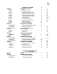
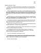
#09610-20012 (ILLUSTRATION 8), disconnect tie rod ends.
9) Locate the four (4) bolts attaching the lower ball joint
on the a-arm to the front spindle (ILLUSTRATION 9). Remove
the four bolts, axle nut and spindle
10) Locate the power steering unit. Disconnect the pressure
feed and return lines at control valve housing. Make sure that
you have a pan to catch the power steering fluid as you discon-
nect these lines. Remove steering unit from chassis.
NOTE: IT IS VERY IMPORTANT TO CENTER
STEERING WHEEL AND LOCK IN THIS POSITION BY RE-
MOVING KEY FROM THE IGNITION. DO NOT UNLOCK OR
ROTATE THE STEERING WHEEL UNTIL YOU HAVE COMPLETED STEP 23 IN INSTRUCTIONS. RO-
TATING THE STEERING WHEEL WITH THE STEERING UNIT DISCONNECTED WILL DAMAGE THE
SPIRAL CABLE IN THE STEERING COLUMN CAUSING THE AIR BAG, HORN AND CRUISE CON-
TROL SYSTEM TO FAIL.
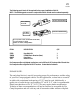
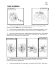
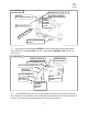
11) Place an index mark on the front and the rear of both adjusting cam-bolts (ILLUSTRATION 10).
Remove nuts, adjusting cam-bolts and lower a-arms.
Repeat steps 5 through 11 on the opposite side, omitting step 10.
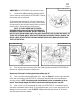
12) Place hoist stand under front differential u-joint. Using the 12mm allen socket, remove mounting
bolt on rear crossmember (ILLUSTRATION 11). Remove the mounting bolts on the front differential
mounting cushions. NOTE: Using hoist stand, raise differential so rear crossmember can be re-
moved. Save existing flanged nut it will be re-used when installing ball joint in step #25.
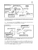
13) Mark “cut lines” on rear crossmember as shown in ILLUSTRATION 12. (Relocate the vacuum
lines behind crossmember before cutting). Using reciprocating saw, cut on cut lines, being careful not to
damage or cut the a-arm boot. Locate the O.E.M. skidplate mount tabs and cut them off. Grind and
clean the cut areas of excess material.
ILLUSTRATION 9
ILLUSTRATION 11 ILLUSTRATION 10
INDEX MARK
INDEX MARK