
Owners manual


9
57095
Revised
2.28.2008
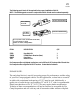
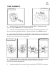
After cutting the crossmember, it is very important that the remaining material on the drivers side rear area
be completely removed to clear the power steering adapter tube. Grind the material flush in the area indi-
cated in (ILLUSTRATION 12).
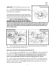
14) Install crossmember support bracket (90-1344) to existing hole location on drivers side of lower a-
arm mount (ILLUSTRATION 13). Use hardware provided. Do not tighten.
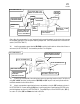
15) Position rear crossmember into existing lower rear a-arm mounting locations (ILLUSTRATION 15)
using 3/4” x 4-1/4” hex bolts, locating washers (90-1345) and 3/4” top lock nuts; loosely fasten with the
bolt heads towards the front of the vehicle.
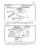
16) Attach crossmember support bracket to rear crossmember, using the 3/8” hardware as shown in
ILLUSTRATION 19. Remove existing O.E.M. stud. Install steering box support bracket (90-1336) using
provided hardware as shown in ILLUSTRATION 16. Torque 3/4” top lock nut to 200-250 ft./lbs., 3/8” ny-
loc nuts to 37 ft./lbs., 9/16” and 14mm. hex bolts to 90 ft./lbs.
EXISTING REAR
CROSSMEMBER
FRAME
CUT
HERE
CUT LINE
SKIDPLATE
TABS
MAKE SURE NOT
TO DAMAGE OR
CUT A-ARM BOOT
See
note
13
CUT LINES ARE 2 1/4”
FROM CENTER LINES
2 1/4 MAX
2 1/4”
POWER STEERING
UNIT MOUNT
ORIGINAL A-ARM
LOCATION
ILLUSTRATION 12
CROSSMEMBER
SUPPORT
BRACKET, 90-1344
TOP LOCK NUT, 9/16”
FLAT WASHER, 9/16”
EXISTING
DRIVERSIDE EXISTING
REAR CROSSMEMBER
FLAT WASHER, 9/16”
HEX BOLT, 9/16” X 1” LG.
ILLUSTRATION 13