For customers who use Pro-face products for the first time – First step of screen creation and settings GP4100 Series Quick Guide 3.4-inch Compact Graphic Operator Interface GP4100 Series www.proface.
GP4100 Series Quick Guide GP4100 Series The GP4100 Series is a 3.4” compact graphic operator interface. This product is recommended to customers who have used interfaces other than graphic operator interfaces, such as digital counters, signal switches and message displays for use on small machine tools, food machinery, packaging machines, monitors for fast chargers, etc. Compact HMI with easy-to-read display. Compact HMI with easy connections.
GP4100 Series Quick Guide How to Get Pro-face Screen Editing Software, GP-Pro EX GP-Pro EX Ver.2.6 or later is required to create HMI screen data for the GP4100 Series. GP-Pro EX provides simple operation with an enhanced user interfaces. - Free upgrade service is available to users of GP-Pro EX Ver.2.0 or later from our support site, Otasuke Pro! (Free member registration is required.) > http://www.pro-face.com/otasuke/ - GP-Pro EX Ver.2.
GP4100 Series Quick Guide How to Use GP-Pro EX GP-Pro EX allows you to create HMI screen data and to configure settings for the GP4100 Series. 1. Start-up and default settings of GP-Pro EX Double-click the icon on the desktop to start GP-Pro EX. After a pop-up window appears, select [New] and specify [Display Unit] and [Orientation] (“Landscape” or “Portrait”).
GP4100 Series Quick Guide Text and Drawings A wide variety of Windows fonts (image fonts) to create easy-to-read screens is available. The drawing feature allows for fine layout with various options for lines and graphics. Make Make use use of of boxes, boxes, lines lines and and circles circles to to create create more more organized organized screens. screens. Small Small characters characters are are clearly clearly displayed displayed with with 200 200 xx 80 80 pixel pixel resolution. resolution.
GP4100 Series Quick Guide Switch and Lamp Make your choice from a wide variety of switches and lamps, such as push buttons and toggle switches. It can be freely placed on the screen by one bit. STOP OK RUN CAUTION NG How to Place Switches and Lamps 1. Place a switch on the base screen Referring to page 4, display [Parts Tool Box] on the main window. Select a switch part from the [Parts Tool Box], and drop and drag it on the base screen.
GP4100 Series Quick Guide Data Display Values stored in a connected device (such as PLC) can be displayed. It also allows for inputting numeric characters and displaying texts too. Voltage Current Display Numeric Data How to Place Data Display 1. Place a Data Display on the base screen Referring to page 4, display [Parts Tool Box] on the main window. Select a Data Display part from the [Parts Tool Box], and drop and drag it on the base screen. 2.
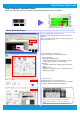
GP4100 Series Quick Guide Graph Display of Operation Status Visually check operation status on screen with numerical information shown in bar or trend graphs. Voltage Current Graph Display How to Place Bar Graphs 1. Place a bar graph on the base screen Referring to page 4, display [Parts Tool Box] on the main window. Select a bar graph from the [Parts Tool Box], and drop and drag it on the base screen. 2. Specify settings for a bar graph Double-click the part to show the setting window.
GP4100 Series Quick Guide Display Error Messages (1) Specify alarm settings to display error messages shown by changes of bit address or data in a connected device. Confirm the error to see a message エラーコード一覧 エラーコード一覧 Error Code List 6B4D 3A7E How to Set Alarms: Register a corresponding message to each bit address When When the the address address M0000 M0000 is is ON, ON, display display ”Press ”Press the the emergency emergency stop stop button.” button.
GP4100 Series Quick Guide Display Error Messages (2) >> IfIf the the [Clock [Clock Update Update Setting] Setting] icon icon is is clicked, clicked, aa GP4100 GP4100 unit unit synchronizes synchronizes its its clock clock with with that that in in aa connected connected device. device. No.1: Over current of the heater The GP4100 Series can be used as a message display, enlarging a message on the entire screen. How to Set Alarms: Specify how to display messages 1.
GP4100 Series Quick Guide Additional Features for Screen Creation The Header/Footer feature allows for reduction of development time. Register a start-up screen to utilize a waiting time during the start-up. Text Table is available for easy creation of screens in multiple languages. 1. Register frequently used parts in header/footer for common use with other screens 1. Set a header and footer Click on the screen to change to the editing screen for header/footer. Click again to return to the base screen. 2.
GP4100 Series Quick Guide Screen Operation Check on PC (Simulation) Screen operations can be tested on a PC before HMI software application is transferred to a GP4100 unit. Neither Neither aa GP4100 GP4100 unit unit nor nor aa USB USB Transfer Transfer Cable Cable is is required required for for the the simulation. simulation. How to Use the Simulation Feature To start a simulation, click the [Simulation] icon or press the [F12] key on PC. (1) [F12] (2) (3) 1.
GP4100 Series Quick Guide Screen Transfer to GP4100 Series Transfer screen data to a GP4100 unit using a USB Transfer Cable or USB flash memory. USB Transfer Cable (USB Type A - mini B) USB Port (mini B) USB Flash Drive USB Port (Type A) (for USB Type A) GP4100 Series Transfer with USB Transfer Cable 1. Start Transfer Tool Click the [Transfer Project] icon to show the Transfer Tool window. 2. Transfer screen data Click the [Send Project] icon to start the transfer.
GP4100 Series Quick Guide Precautions for Installation Use an installation fastener to install a GP4100 unit on a operation panel and make wire connections for power and communication cables. (Caution: To prevent electric shock, please make sure the power is not supplied while the above installations are made.
GP4100 Series Quick Guide Precaution for USB Cable Clamp (sold separately) Two types of USB Cable Clamp: for Type A and for mini B. This clamp is used to prevent a USB cable connected to USB Interface of a GP unit from being unplugged due to vibration or other causes. - When a USB Cable Clamp for Type A is used, remove a USB cover from a USB holder prior to the installation.
GP4100 Series Quick Guide “Otasuke Pro!” supports you with a full range of services! > http://www.pro-face.com/otasuke/ The content of our “Otasuke Pro!” support site has been upgraded with services aimed at reducing development time by including contents such as Q&A and manual downloads. Our Support site is designed to help you Maximize the value of your Pro-face HMI.