
Installation guide


14
4. Input/Output Signal Line Cautions
• All LT Input and Output signal lines must
be separated from all operating circuit
(power) cables.
• If this is not possible, use a shielded cable
and ground the shield.
5. Wiring Precautions
• To help prevent noise and interference
problems, separate all control, communica-
tion and power lines by placing them in a
separate ducts.
If different wires must be placed in the same
duct, separate them with an earthed/grounded
divider.
• If the lines cannot be separated, use
shielded lines and create a ground from the
shield line.
• Use noise-reducing external wiring
methods to increase overall system
reliability.
• To prevent power surges or noise inter-
ference, use ducts to separate all DC I/O
or current circuit wires from communi-
cation cables.
• To prevent malfunctions due to noise,
communication cables must be wired
separately from high-frequency lines
and power lines such as high-voltage
lines, high-current lines, and inverters.
To prevent the USB cable
from coming off
• When using USB Host Interface in
Hazardous Locations provided in
ANSI/ISA-12.12.01-2007, please fix
the USB cable with the USB Holder. If
it’s not fixed so that the connector on
the LT’s side and the PLC’s side can-
not come out, the USB Host Interface
cannot be used in the Hazardous
Locations.
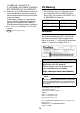
Attaching the USB Holder
(1) Before starting the procedure, pull out the
USB cover from the USB holder by hold-
ing the top and bottom of the USB holder
and pressing down the tab on the USB
cover.
(2) With the main unit display part
positioned so that it is facing down,
attach the USB holder to the USB host
interface. Insert the picks on the top of
the USB holder into the attachment holes
on the main unit, and then insert the
holder into the USB host interface so that
the holder is secured in the main unit.
Duct for I/O Sig-
nal Lines
Duct for Control
Lines
Duct for Power
Lines
I/O Signal
Lines
Control
Lines
Power
Lines
Grounded
Separators
Duct (non-
conducting
resin/plas-
tic)
Earth/Ground
cPress down the tab,
dAnd pull out
the USB cover.
Attachment Hole