
Hardware manual


LT-4201TM/4301TM Hardware Manual
101
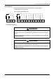
The figure shows the group and the signal name of the terminal blocks:
Pin Arrangement Group Pin Signal
Name
Group Pin Signal
Name
Fast Input/
Standard Input
C1 I0 Fast Input/
Standard Input
D1 IC0
C2 I1 Standard Input D2 I2
C3 I3 D3 IC1
Standard Input C4 I5 D4 I4
C5 I7 D5 I6
C6 I9 D6 I8
C7 I11 D7 I10
Temperature
Input
C8 MS0
+ Temperature
Input
D8 MS0-
C9 EX0+ D9 EX0-
C10 MS1+ D10 MS1-
C11 EX1+ D11 EX1-
Analog Input C12 IV0 Analog Input D12 AIC
C13 IV1 D13 IA0
C14 IA1 Analog Output D14 AOC
Analog Output C15 U/I0 D15 U/I1
&
&
'
'
DANGER
HAZARD OF ELECTRIC SHOCK, EXPLOSION OR ARC FLASH
z Disconnect all power from all equipment including connected devices prior to
removing any covers or doors, or installing or removing any accessories,
hardware, cables, or wires except under the specific conditions specified in the
appropriate hardware guide for this equipment.
z Always use a properly rated voltage sensing device to confirm the power is off
where and when indicated.
z Replace and secure all covers, accessories, hardware, cables, and wires and
confirm that a proper ground connection exists before applying power to the
unit.
z Use only the specified voltage when operating this equipment and any
associated products.
Failure to follow these instructions will result in death or serious injury.