
Hardware manual


LT-4201TM/4301TM Hardware Manual
103
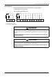
Wiring Diagram
The figure describes the wiring diagram of the LTs digital inputs.
Terminal Blocks (see page 100).
Hig
h-speed Input/Standard Input:
±
,,& , , , , , , , ,
&' ' & ' & ' & ' &
E
D
±
±
,,& , ,
&
D6LQNLQSXWVSRVLWLYHORJLF
E6RXUFHLQSXWVQHJDWLYHORJLF
' & '
E
D
±
WARNING
UNINTENDED EQUIPMENT OPERATION
Do not connect wires to unused terminals or terminals marked “No
t Connected
(N.C.)”.
Failure to follow these instructions can result in death, serious injury, or
equ
ipment damage.
WARNING
UNINTENDED EQUIPMENT OPERATION
Use a single power source fo
r the sensor and actuator.
Failure to follow these instructions can result in death, serious injury, or
equ
ipment damage.