
Hardware manual


LT-4201TM/4301TM Hardware Manual
119
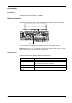
Pin Assignment
The figure shows the RJ45 Ethernet connector pin assignment:
The table describes the RJ45 Ethernet connecto
r pins:
NOTE: The LT supports the MDI/MDIX auto-crossover cable function. You
do not
have to use special Ethernet crossover cables to connect devices directly to this port
(connections without an Ethernet hub or switch).
Status LEDs
The table describes the Ethernet LEDs operations:
Pin Signal
1 TD+
2 TD-
3 RD+
4 –
5 –
6 RD-
7 –
8 –
Label Description LED
Color Status Description
IND1 Ethernet status Green Off No connection or subsequent
transmission failure.
On Data transmission is a
vailable
IND2 Ethernet activity Green Off No data transmission
On Data transmission is occurring