
Installation guide


10
(4) Remove the flathead screwdriver from
the tool insertion hole (square-shaped
hole). The wire insertion hole (round-
shaped hole) will close and the wire will
be secured. In the case of wire removal,
remove the desired wire by inserting a
flathead screwdriver into the correspond-
ing tool insertion hole (square-shaped
hole) following procedures (1) and (2).
(5) Insert the wired DIO connector straight
into the DIO I/F of the LT unit.
• Be sure to strip only the amount of
cover required. If too much cover is
removed, the end wires may short
against each other, or against an elec-
trode, which can create an electric
shock. If not enough cover is removed
the wire cannot carry a charge.
• Do not solder the wire itself. This could
lead to a bad or poor contact.
• Insert each wire completely into its
opening. Failure to do so can lead to a
unit malfunction or short, either against
wire filaments, or against an electrode.
• When wiring, be aware of the installa-
tion position, direction, and twisting of
the wiring as to not develop stress on
the connector. Fix the cable near the
LT by cable clamp and set it loosely as
to not place tension on the connector.
Wiring
y To avoid an electric shock, prior to
connecting the LT unit’s power cord
terminals to the power terminal block,
confirm that the LT unit’s power supply
is completely turned OFF, via a
breaker, or similar unit.
y Any other power level can damage
both the LT and the power supply.
y When the FG terminal is connected, be
sure the wire is grounded.
1. Wiring the DC type power supply
cable
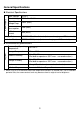
Power Cord Specifications
Use copper conductors only.
Power Connector (Plug) Specifications
Power Cord
Diameter
0.75 to 2.5mm
2
(18 - 12 AWG)
Conductor
Type
Simple or Stranded Wire
*1
*1 If the Conductor’s end (individual) wires are
not twisted correctly, the end wires may either
short against each other, or against an
electrode.
Conductor
Length
+ 24V
-
0V
FG
Grounding
Terminal
connected
to the LT
chassis
7 mm
[0.28in]
+
−
FG
Insertion
Direction