
Installation guide


7
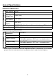
LT3201-A1-D24-C Output Circuit (Source type)
• Since the output terminals are not electrically protected, an output line might be short-cir-
cuited or a connection fault might damage the LT unit. Please install an applicable fuse to pre-
vent an overload in the circuit, if necessary.
High-Speed Counter / Pulse Catch Input Specifications
DIO Standard Input/Output is used as a High-Speed Counter Input. The setup is done by the
GP-Pro EX. GP-Pro EX Reference Manual “Controlling External I/O”
Counter Pulse Catch
Input
DC24V Open Collector
DC24V Open Collector
Single Phase
(4 points)
2 Phase
(1 point or 2 points)
Input Points
CT0 (IN0),
CT1 (IN2),
CT2 (IN4),
CT3 (IN6)
CT0 (IN0), CT1 (IN2)
(used as pair)
CT0: A Phase,
CT1: B Phase
CT2 (IN4), CT3 (IN6)
(used as pair)
CT2: A Phase,
CT3: B Phase
IN0, IN2,
IN4, IN6
High Speed Count
Frequency
100Kpps 50Kpps ⎯
Marker Input
(Counter Value Clear)
None IN3, IN7 ⎯
L
L
Internal Circuit
Internal Circuit
Fuse
2.5A
DC 24V
External
Power
+24V B8
0V A8
OUT5 A11
OUT4 B11
OUT3 A10
OUT2 B10
OUT1 A9
OUT0 B9
+
-
Dummy
Resistor
*1
*1 (Example) The output delay time (ON to OFF) is 1.5µs where the output current is
DC 24V, 50mA. Install an external dummy resistor to increase the amount of
current when more responsiveness is required and the load is light.
SEE