Model No. PFEVEX71910.0 Serial No. Write the serial number in the space above for reference. USER'S MANUAL Serial Number Decal (under frame) QUESTIONS? If you have questions, or if there are missing parts, please contact us: UK Call: 08457 089 009 From Ireland: 053 92 36102 Website: www.iconsupport.eu E-mail: csuk@iconeurope.com Write: ICON Health & Fitness, Ltd. c/o HI Group PLC Express Way Whitwood, West Yorkshire WF10 5QJ UK AUSTRALIA Call: 1-800-237-173 E-mail: australiacc@iconfitness.
TABLE OF CONTENTS WARNING DECAL PLACEMENT . . . . . . . . . . . . . . . . . . . . . . . . . . . . . . . . . . . . . . . . . . . . . . . . . . . . . . . . . . . . . .2 IMPORTANT PRECAUTIONS . . . . . . . . . . . . . . . . . . . . . . . . . . . . . . . . . . . . . . . . . . . . . . . . . . . . . . . . . . . . . . . .3 BEFORE YOU BEGIN . . . . . . . . . . . . . . . . . . . . . . . . . . . . . . . . . . . . . . . . . . . . . . . . . . . . . . . . . . . . . . . . . . . . . .4 ASSEMBLY . . . . . . . . . . . . .
IMPORTANT PRECAUTIONS WARNING: To reduce the risk of serious injury, read all important precautions and instructions in this manual and all warnings on your exercise bike before using your exercise bike. ICON assumes no responsibility for personal injury or property damage sustained by or through the use of this product. 1. Before beginning any exercise program, consult your physician. This is especially important for persons over age 35 or persons with pre-existing health problems. 8.
BEFORE YOU BEGIN Thank you for selecting the new PROFORM® 100 ZLX exercise bike. Cycling is an effective exercise for increasing cardiovascular fitness, building endurance, and toning the body. The 100 ZLX exercise bike provides an impressive selection of features designed to make your workouts at home more effective and enjoyable. after reading this manual, please see the front cover of this manual. To help us assist you, note the product model number and serial number before contacting us.
ASSEMBLY Assembly requires two persons. Place all parts of the exercise bike in a cleared area and remove the packing materials. Do not dispose of the packing materials until assembly is completed. In addition to the included tool(s), assembly requires a Phillips screwdriver wrench , and a rubber mallet . , an adjustable See the drawings below to identify the small parts needed for assembly.
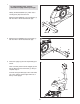
1. 1 To make assembly easier, read the information on page 5 before you begin. Identify the Rear Stabilizer (14), which has a Leveling Foot (63) near each end. Attach the Rear Stabilizer (14) to the Frame (1) with two M10 x 75mm Patch Screws (36). 14 63 1 36 2. Attach the Front Stabilizer (2) to the Frame (1) with two M10 x 75mm Patch Screws (36). 63 2 2 36 1 3. Orient the Upright (3) and the Top Shield (9) as shown.
4. Tip: Avoid pinching the wires. Slide the Upright (3) onto the Frame (1). 4 Attach the Upright (3) with four M8 x 18mm Patch Screws (35). Avoid pinching the wires Slide the Top Shield (9) downward and press it onto the Left and Right Shields (17, 18). 9 3 35 17 1 18 5. Orient the Seat (12) and the Seat Carriage (67) as shown. 5 Attach the Seat (12) to the Seat Carriage (67) with four M8 Locknuts (37). Note: The Locknuts may be preattached to the underside of the Seat.
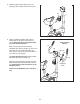
6. Orient the Seat (12) assembly and the Seat Post (5) as shown. Then, loosen the Seat Knob (69). 6 Slide the Seat Carriage (67) onto the Seat Post (5). Then, slide the Seat Carriage all the way forward and tighten the Seat Knob (69). 5 12 67 69 Attach an M6 x 10mm Button Screw (68) to the rear of the Seat Post (5). 68 12 7. Using an adjustable wrench, tighten a Seat Post Knob (11) into the Frame (1).
8. Attach the Water Bottle Holder (49) to the Upright (3) with two M4 x 22mm Screws (54). 8 49 3 54 9. Identify the Right Handlebar (48), which is marked with an “R” sticker, and orient it as shown. Make sure that the hexagonal holes are in the indicated location. 9 Avoid pinching the wire 47 While a second person holds the Right Handlebar (48) near the Upright (3), tie the indicated wire tie to the Right Pulse Wire (64).
. The Console (6) can use four D batteries (not included); alkaline batteries are recommended. IMPORTANT: If the Console has been exposed to cold temperatures, allow it to warm to room temperature before inserting batteries. Otherwise, you may damage the console displays or other electronic components. Remove the screws, remove the battery covers, and insert the batteries into the battery compartments. Make sure to orient the batteries as shown by the diagrams inside the battery compartments.
12. Attach the Handlebar Cover (19) to the Upright (3) with two M4 x 16mm Screws (40). 12 19 40 3 13. Identify the Right Pedal (26), which is marked with an “R.” Using an adjustable wrench, firmly tighten the Right Pedal (26) clockwise into the right arm of the Crank (13). 13 Tighten the Left Pedal (not shown) counterclockwise into the left arm of the Crank (not shown).
HOW TO USE THE EXERCISE BIKE HOW TO ADJUST THE HEIGHT OF THE SEAT HOW TO ADJUST THE PEDAL STRAPS For effective exercise, the seat should be at the proper height. As you pedal, there should be a slight bend in your knees when the pedals are in the lowest position. To adjust the pedal straps, first pull the ends of the straps off the tabs on the pedals. Then, adjust the straps to the desired position, and press the ends of the straps onto the tabs.
CONSOLE DIAGRAM FEATURES OF THE CONSOLE For example, lose unwanted pounds with the 8-week Weight Loss workout. iFit workouts control the resistance of the pedals while the voice of a personal trainer coaches you through your workouts. iFit cards are available separately. To purchase iFit cards, go to www.iFit.com or call the telephone number on the front cover of this manual. iFit cards are also available at select stores.
HOW TO USE THE MANUAL MODE 4. Follow your progress with the display. 1. Turn on the console. The left display–This display can show the elapsed time and the approximate number of calories you have burned. The display will change modes every few seconds. Press any button or begin pedaling to turn on the console. When you turn on the console, the display will light. A tone will sound and the console will be ready for use.
5. Measure your heart rate if desired. HOW TO USE A PRESET WORKOUT If there are sheets of plastic on the Contacts metal contacts on the handgrip pulse sensor, remove the plastic. In addition, make sure that your hands are clean. To measure your heart rate, hold the handgrip pulse sensor with your palms resting against the metal contacts. Avoid moving your hands or gripping the contacts tightly. 1. Turn on the console. See step 1 on page 14. 2. Select a preset workout.
HOW TO USE AN IFIT WORKOUT During the workout, the workout profile will show your progress (see the drawing on page 15). The flashing segment of the profile represents the current segment of the workout. The height of the flashing segment indicates the resistance level for the current segment. iFit cards are available separately. To purchase iFit cards, go to www.iFit.com or see the front cover of this manual. iFit cards are also available at select stores. 1. Turn on the console.
HOW TO USE THE SOUND SYSTEM To play music or audio books through the console sound system while you exercise, plug the included audio cable into the jack on the console and into a jack on your MP3 player or CD player; make sure that the audio cable is fully plugged in. The center display will show the selected unit of measurement. An E for English miles or an M for metric kilometers will appear in the display. To change the unit of measurement, press the Resistance increase button repeatedly.
MAINTENANCE AND TROUBLESHOOTING Locate the Reed Switch (21). Turn the Pulley (13) until a Pulley Magnet (16) is aligned with the Reed Switch. Loosen, but do not remove, the indicated M4 x 16mm Screw (40). Slide the Reed Switch slightly closer to or away from the Magnet, and then retighten the Screw. Inspect and tighten all parts of the exercise bike regularly. Replace any worn parts immediately. To clean the exercise bike, use a damp cloth and a small amount of mild soap.
HOW TO ADJUST THE DRIVE BELT Remove all the screws from the left and right shields; there are two sizes of screws in the shields—note which size of screw you remove from each hole. Then, gently pull the right shield away from the frame. If the pedals slip while you are pedaling, even while the resistance is adjusted to the highest setting, the drive belt may need to be adjusted. Loosen the M6 x 20mm Hex Screw (60). Then, tighten the M10 x 50mm Hex Screw (33) until the Drive Belt (23) is tight.
EXERCISE GUIDELINES WARNING: Burning Fat—To burn fat effectively, you must exercise at a low intensity level for a sustained period of time. During the first few minutes of exercise, your body uses carbohydrate calories for energy. Only after the first few minutes of exercise does your body begin to use stored fat calories for energy. If your goal is to burn fat, adjust the intensity of your exercise until your heart rate is near the lowest number in your training zone.
SUGGESTED STRETCHES The correct form for several basic stretches is shown at the right. Move slowly as you stretch—never bounce. 1. Toe Touch Stretch 1 Stand with your knees bent slightly and slowly bend forward from your hips. Allow your back and shoulders to relax as you reach down toward your toes as far as possible. Hold for 15 counts, then relax. Repeat 3 times. Stretches: Hamstrings, back of knees and back. 2. Hamstring Stretch 2 Sit with one leg extended.
PART LIST—Model No. PFEVEX71910.0 Key No. Qty. 1 2 3 4 5 6 7 8 9 10 11 12 13 14 15 16 17 18 19 20 21 22 23 24 25 26 27 28 29 30 31 32 33 34 35 36 1 1 1 2 1 1 1 1 1 2 1 1 1 1 2 2 1 1 1 1 1 1 1 1 1 1 1 1 1 1 1 1 1 2 4 4 Description Key No. Qty.
EXPLODED DRAWING—Model No. PFEVEX71910.
ORDERING REPLACEMENT PARTS To order replacement parts, see the front cover of this manual.