www.proform.com Model No. PFTL01411.0 Serial No. Write the serial number in the space above for reference. Serial Number Decal QUESTIONS? If you have questions, or if parts are damaged or missing, DO NOT CONTACT THE STORE; please contact Customer Care. IMPORTANT: Please register this product (see the limited warranty on the back cover of this manual) before contacting Customer Care. 1-888-533-1333 CALL TOLL-FREE: Mon.–Fri. 6 a.m.–6 p.m. MT Sat. 8 a.m.–4 p.m. MT ON THE WEB: www.proformservice.
TABLE OF CONTENTS WARNING DECAL PLACEMENT . . . . . . . . . . . . . . . . . . . . . . . . . . . . . . . . . . . . . . . . . . . . . . . . . . . . . . . . . . . . . .2 IMPORTANT PRECAUTIONS . . . . . . . . . . . . . . . . . . . . . . . . . . . . . . . . . . . . . . . . . . . . . . . . . . . . . . . . . . . . . . . .3 BEFORE YOU BEGIN . . . . . . . . . . . . . . . . . . . . . . . . . . . . . . . . . . . . . . . . . . . . . . . . . . . . . . . . . . . . . . . . . . . . . .5 ASSEMBLY . . . . . . . . . . . . .
IMPORTANT PRECAUTIONS WARNING: To reduce the risk of serious injury, read all important precautions and instructions in this manual and all warnings on your treadmill before using your treadmill. ICON assumes no responsibility for personal injury or property damage sustained by or through the use of this product. 1. Before beginning any exercise program, consult your physician. This is especially important for persons over age 35 or persons with pre-existing health problems. carrying 15 or more amps.
24. Inspect and properly tighten all parts of the treadmill regularly. 20. Never leave the treadmill unattended while it is running. Always remove the key, unplug the power cord, and press the power switch into the off position when the treadmill is not in use. (See the drawing on page 5 for the location of the power switch.) 25. 21. Do not attempt to raise, lower, or move the treadmill until it is properly assembled. (See ASSEMBLY on page 6, and HOW TO FOLD AND MOVE THE TREADMILL on page 25.
BEFORE YOU BEGIN Thank you for selecting the revolutionary PROFORM® 1210 RT treadmill. The 1210 RT treadmill offers an impressive selection of features designed to make your workouts at home more enjoyable and effective. And when youʼre not exercising, the unique treadmill can be folded up, requiring less than half the floor space of other treadmills. ing this manual, please see the front cover of this manual.
ASSEMBLY Assembly requires two persons. Set the treadmill in a cleared area and remove all packing materials. Do not dispose of the packing materials until assembly is completed. Note: The underside of the treadmill walking belt is coated with high-performance lubricant. During shipping, some lubricant may be transferred to the top of the walking belt or the shipping carton. This is normal and does not affect treadmill performance.
1. Make sure that the power cord is unplugged. 1 With the help of a second person, carefully tip the treadmill onto its left side. Partially fold the Frame (55) so that the treadmill is more stable; do not fully fold the Frame yet. Tie Hole 85 94 55 Locate the Upright Wire (85), which is bundled at the back of the Base (94). Remove the packaging from the Upright Wire. Next, insert the Upright Wire into the Base, and pull it out of the indicated hole.
3. Identify the Right Upright Spacer (91), which is marked with a “Right” sticker. 3 Align the oval hole in the Right Upright Spacer (91) with the oval hole in the Base (94). If the holes do not line up, turn the Right Upright Spacer and try again. Oval Hole 85 91 Oval Hole Insert the Upright Wire (85) through the Right Upright Spacer (91). Set the Right Upright Spacer on the Base (94). 4. Identify the Right Upright (83), which is marked with a “Right” sticker.
5. Hold a Screw Spacer (88) inside the lower end of the Right Upright (83). Insert a 3/8" x 5 1/2" Screw (7) with a 3/8" Star Washer (11) into the Right Upright and the Screw Spacer. Repeat this step with a second Screw Spacer (88), 3/8" x 5 1/2" Screw (7), and 3/8" Star Washer (11). 5 Hold the Right Upright (83) against the Right Upright Spacer (91). Be careful not to pinch the Upright Wire (85) or the ground wire.
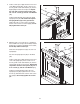
7. Attach the Base Cover (84) to the Base (94) with four #8 x 1/2" Screws (1). Be careful not to overtighten the Screws. 7 84 With the help of a second person, tip the treadmill so that the Base (94) is flat on the floor. 94 1 1 8. Set the console assembly face down on a soft surface to avoid scratching the console. 8 Identify the Right Handrail (79). Hold the Right Handrail near the console assembly. Route the console wire through the large holes in the top and bottom of the Right Handrail.
9. With the help of a second person, grip the sides of the console assembly and hold it near the Right Upright (83) and the Left Upright (not shown). Do not lift the console assembly by the Right Handrail (79) or the Left Handrail (not shown). 9 Connect the Upright Wire (85) to the console wire. See the inset drawing. The connectors should slide together easily and snap into place. If they do not, turn one connector and try again.
11. Start two 1/4" x 1/2" Screws (8) into the lower ends of both Handrails (78, 79). Tighten all fourteen Screws (4, 5, 8). 11 Console Assembly Slide the Handrail Covers (77) against the Uprights (82, 83). 4 4 5 8 5 79 8 8 77 82 83 12. See steps 5 and 6. Tighten the four 3/8" x 5 1/2" Screws (7). Attach the Left Accessory Tray (101) and the Right Accessory Tray (104) to the console assembly with eight #8 x 1/2" Screws (1).
. Turn on the power (see page 16). Next, adjust the incline to the lowest position (see step 4 on page 17). Then, remove the key from the console, press the power switch into the off position, and unplug the power cord. 13 55 Latch Knob Raise the Frame (55) to the position shown. Have a second person hold the Frame until step 14 is completed. 51 Orient the Storage Latch (51) so that the large barrel and the latch knob are in the positions shown.
OPERATION AND ADJUSTMENT HOW TO PLUG IN THE POWER CORD DANGER: Improper connection of the equipment-grounding conductor increases the risk of electric shock. Check with a qualified electrician or serviceman if you are unsure whether the product is properly grounded. Do not modify the plug—if it will not fit the outlet, have a proper outlet installed by a qualified electrician. This product is for use on a nominal 120-volt circuit (see drawing 1).
CONSOLE DIAGRAM Audio Jack FEATURES OF THE CONSOLE The treadmill console offers an impressive array of features designed to make your workouts more effective and enjoyable. When the manual mode of the console is selected, you can change the speed and incline of the treadmill with the touch of a button. As you exercise, the console will display continuous exercise feedback. You can even measure your heart rate using the handgrip heart rate monitor.
HOW TO TURN ON THE POWER HOW TO USE THE MANUAL MODE IMPORTANT: If the treadmill has been exposed to cold temperatures, allow it to warm to room temperature before turning on the power. If you do not do this, you may damage the console displays or other electrical components. Plug in the power cord (see page 14). Next, locate the reset/off circuit breaker on the treadmill frame near the power cord. Make sure that the circuit breaker is in the reset position. 1. Insert the key into the console.
If you press one of the numbered speed buttons, the walking belt will gradually change speed until it reaches the selected speed setting. To select a speed setting that includes a decimal—such as 3.5 mph—press two numbered buttons in succession. For example, to select a speed setting of 3.5 mph, press the 3 button and then immediately press the 5 button.
6. Measure your heart rate if desired. Before using the handgrip heart rate monitor, remove the sheets of plastic from the metal contacts, if necessary. In addition, make sure that your hands are clean. HOW TO USE A SET-A-GOAL WORKOUT 1. Insert the key into the console. See step 1 on page 16. 2. Select the start menu. See step 2 on page 16. Contacts 3. Select a set-a-goal workout. To select a set-a-goal workout, first press the Workouts button on the screen. Then, press the Set a Goal button.
5. Monitor your progress. HOW TO USE A CALORIE BURN WORKOUT OR AN ALL-TERRAIN TRAILS WORKOUT See step 5 on page 17. The screen can also show your goal and a status bar showing your progress toward your goal. 1. Insert the key into the console. See step 1 on page 16. 6. Measure your heart rate if desired. 2. Select the start menu. See step 6 on page 18. See step 2 on page 16. 7. Turn on the fan if desired. 3. Select a calorie burn workout or an all-terrain trails workout. See step 7 on page 18. 8.
4. Start the workout. screen. To pause the workout, press the Pause button. To end the workout and select a new workout, press the New Workout button. To end the workout, press the End Workout button. Press the Start Workout button to start the workout. A moment after you press the button, the walking belt will begin to move. Hold the handrails and begin walking. To continue the workout, press the Resume button or the Start button. The walking belt will begin to move at 1 mph.
HOW TO USE THE IFIT LIVE MODE HOW TO USE THE STEREO SOUND SYSTEM The iFit Live mode enables the treadmill to communicate with your wireless network. With the iFit Live mode, you can download personalized workouts, create your own workouts, track your workout results, and access many other features. See www.iFit.com for complete information. To play music or audio books through the consoleʼs speakers, you must connect your MP3 player, CD player, or other personal audio player to the console.
HOW TO USE THE SETTINGS MODE 2b. Connect your treadmill to an encrypted wireless network. The console features a settings mode that allows you to connect your treadmill to your own wireless network and to log in to your iFit Live account. The settings mode also allows you to turn on and turn off the display demo mode. You may also be able to select the unit of measurement.
To use a static DNS, press the Use Static DNS button. Enter at least one DNS. Press the arrow buttons to view additional entry boxes. When you are finished, press the Submit button. To return to the Advanced Settings screen, press the Cancel button. To set up an iFit Live account, or for more information about the account, go to www.iFit.com. 4. Turn on or turn off the display demo mode. The console features a display demo mode, designed to be used if the treadmill is displayed in a store.
HOW TO USE THE MAINTENANCE MODE The console features a maintenance mode that allows you to calibrate the incline and speed of the treadmill, restore factory defaults, calibrate the screen, update the console software, and view technical information. 5. Calibrate the screen. If the screen is not properly calibrated, it will be difficult for you to press the buttons on the screen. To calibrate the screen, press the Calibrate Screen button and then press the Begin button.
HOW TO FOLD AND MOVE THE TREADMILL HOW TO FOLD THE TREADMILL HOW TO MOVE THE TREADMILL To avoid damaging the treadmill, adjust the incline to the lowest position before you fold the treadmill. Then, remove the key and unplug the power cord. CAUTION: You must be able to safely lift 45 lbs. (20 kg) to raise, lower, or move the treadmill. Before moving the treadmill, fold it as described at the left. CAUTION: Make sure that the latch knob is locked in the storage position.
TROUBLESHOOTING Most treadmill problems can be solved by following the simple steps below. Find the symptom that applies, and follow the steps listed. If further assistance is needed, see the front cover of this manual. c. Remove the key from the console, and then reinsert it. d. If the treadmill still will not run, please see the front cover of this manual. SYMPTOM: The power does not turn on SYMPTOM: The console displays remain lit when you remove the key from the console a.
Remove the four #8 x 3/4" Screws (14), and carefully remove the Motor Hood (61). 61 14 a. Use only a single-outlet surge suppressor that meets all of the specifications described on page 14. b. If the walking belt is overtightened, treadmill performance may decrease and the walking belt may become damaged. Remove the key and UNPLUG THE POWER CORD. Using the hex key, turn both idler roller screws counterclockwise, 1/4 of a turn.
SYMPTOM: The walking belt is off-center or slips when walked on b. If the walking belt slips when walked on, first remove the key and UNPLUG THE POWER CORD. Using the hex key, turn both idler roller screws clockwise, 1/4 of a turn. When the walking belt is correctly tightened, you should be able to lift each edge of the walking belt 2 to 3 in. (5 to 7 cm) off the walking platform. Be careful to keep the walking belt centered.
EXERCISE GUIDELINES WARNING: Before beginning this Burning Fat—To burn fat effectively, you must exercise at a low intensity level for a sustained period of time. During the first few minutes of exercise, your body uses carbohydrate calories for energy. Only after the first few minutes of exercise does your body begin to use stored fat calories for energy. If your goal is to burn fat, adjust the intensity of your exercise until your heart rate is near the lowest number in your training zone.
PART LIST Key No. Qty. 1 2 3 4 5 6 7 8 9 10 11 12 13 14 15 16 17 18 19 20 21 22 23 24 25 26 27 28 29 30 31 32 33 34 35 36 37 38 39 40 41 42 43 44 45 46 47 48 49 50 14 4 1 6 4 1 4 4 8 5 4 2 1 36 2 2 8 12 4 2 4 2 4 1 2 2 2 6 2 4 4 1 2 4 1 1 2 1 2 1 1 1 1 1 1 1 1 1 1 1 Description Key No. Qty.
Key No. Qty. 101 102 103 104 105 1 1 1 1 1 Description Key No. Qty. Left Accessory Tray Console Base Wire Tie Clamp Right Accessory Tray Access Door 106 107 108 * 1 3 1 – Description Pulse Bar Pulse Ground Wire Site Warning Decal Userʼs Manual Note: Specifications are subject to change without notice. For information about ordering replacement parts, see the back cover of this manual. *These parts are not illustrated.
18 32 15 26 25 30 23 59 14 36 35 60 15 58 37 25 28 18 57 26 38 30 56 23 28 28 39 14 19 55 18 18 40 30 23 48 43 28 6 42 37 41 44 20 21 28 45 17 51 19 46 50 18 54 39 30 18 10 23 17 32 24 47 53 1 21 33 3 EXPLODED DRAWING A Model No. PFTL01411.
EXPLODED DRAWING B Model No. PFTL01411.
EXPLODED DRAWING C Model No. PFTL01411.
EXPLODED DRAWING D 98 99 14 14 14 Model No. PFTL01411.
ORDERING REPLACEMENT PARTS To order replacement parts, please see the front cover of this manual.