
Operation Manual


8
8. Make sure that all parts are properly tightened before you use the treadmill. Note: Extra hardware may
be included. Keep the included hex keys in a secure place. The large hex key is used to adjust the walking
belt (see page 16). To protect the floor or carpet, place a mat under the treadmill.
47
42
44
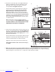
7. Insert the excess Wire Harness (42) into the large hole in
the side of the Right Handrail (72). Securely tighten the
nylon ties on the bottom of the Console Base (47) to
prevent the Wire Harness from slipping. Then, cut off
the ends of the nylon ties.
Route the Wire Harness (42) through the indicated open-
ing in the Console Base (47). Attach the Wire Cover (44)
to the Console Base with a 1/2” Silver Screw (48).
Tighten two 3/4” Screws (2) into the Console Base (47).
Firmly tighten the bolts and screws used in steps 2,
3, 4, and 6.
7
2
72
48
Ties
Opening
47
Ties
72
6
6. Place the Console Base (47) on the Right Handrail (72)
and the Left Handrail (not shown). Attach the Console
Base with four 3/4” Screws (2) (only two Screws are
shown).
Do not overtighten the Screws.
Insert the Wire Harness (42) through the two indicated
nylon ties on the Console Base (47). Next, touch the
Right Handrail (72) to discharge any static. Refer to
drawing 6c. Find the connector on the end of the Wire
Harness (42). Insert the connector into the red socket be-
neath the Console (43). The connector should slide eas-
ily into the socket and snap into place.
If the connector
does not slide easily and snap into place, turn the connec-
tor and then insert it.
Make sure that the connector and wires appear as
shown in drawing 6a. IF THE CONNECTOR IS NOT IN-
SERTED PROPERLY, THE CONSOLE MAY BE DAM-
AGED WHEN THE POWER IS TURNED ON.
42
43
2
42
6a
Downloaded from www.Manualslib.com manuals search engine