Model No. PFEVEL74910.0 Serial No. Write the serial number in the space above for reference. USERʼS MANUAL Serial Number Decal QUESTIONS? If you have questions, or if there are missing parts, please contact us: UK Call: 08457 089 009 From Ireland: 053 92 36102 Website: www.iconsupport.eu E-mail: csuk@iconeurope.com Write: ICON Health & Fitness, Ltd. c/o HI Group PLC Express Way Whitwood, West Yorkshire WF10 5QJ UK AUSTRALIA Call: 1-800-237-173 E-mail: australiacc@iconfitness.
TABLE OF CONTENTS WARNING DECAL PLACEMENT . . . . . . . . . . . . . . . . . . . . . . . . . . . . . . . . . . . . . . . . . . . . . . . . . . . . . . . . . . . . . .2 IMPORTANT PRECAUTIONS . . . . . . . . . . . . . . . . . . . . . . . . . . . . . . . . . . . . . . . . . . . . . . . . . . . . . . . . . . . . . . . .3 BEFORE YOU BEGIN . . . . . . . . . . . . . . . . . . . . . . . . . . . . . . . . . . . . . . . . . . . . . . . . . . . . . . . . . . . . . . . . . . . . . .4 ASSEMBLY . . . . . . . . . . . . .
IMPORTANT PRECAUTIONS WARNING: To reduce the risk of serious injury, read all important precautions and instructions in this manual and all warnings on your elliptical before using your elliptical. ICON assumes no responsibility for personal injury or property damage sustained by or through the use of this product. 1. Before beginning any exercise program, consult your physician. This is especially important for persons over age 35 or persons with pre-existing health problems. 9.
BEFORE YOU BEGIN Thank you for selecting the new PROFORM® 400 ZLE elliptical. The 400 ZLE elliptical provides a selection of features designed to make your workouts at home more effective and enjoyable. manual. To help us assist you, note the product model number and serial number before contacting us. The model number and the location of the serial number decal are shown on the front cover of this manual. For your benefit, read this manual carefully before you use the elliptical.
ASSEMBLY Assembly requires two persons. Place all parts of the elliptical in a cleared area and remove the packing materials. Do not dispose of the packing materials until assembly is completed. In addition to the included tool(s), assembly requires a Phillips screwdriver adjustable wrench . and an See the drawings below to identify the small parts needed for assembly. The number in parentheses below each drawing is the key number of the part, from the PART LIST near the end of this manual.
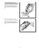
1. 1 To make assembly easier, read the information on page 5 before you begin. While a second person lifts the rear of the Frame (1), attach the Rear Stabilizer (70) to the Frame with two M10 x 85mm Patch Screws (82). 70 1 82 2. Orient the Front Stabilizer (73) so that the “Front” sticker is facing away from the Frame (1). 2 While a second person lifts the front of the Frame (1), attach the Front Stabilizer (73) to the Frame with two M10 x 85mm Patch Screws (82).
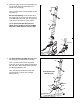
3. Orient the Upright (2) and the Top Shield Cover (37) as shown. Slide the Top Shield Cover upward onto the Upright. 3 Wire Tie Have a second person hold the Upright (2) near the Frame (1). See the inset drawing. Locate the wire tie in the Upright (2). Tie the lower end of the wire tie to the Main Wire (42). Then, pull the upper end of the wire tie out of the top of the Upright.
5. Orient the Console Cover (32) as shown. 5 Insert the Main Wire (42) upward through the Console Cover (32). Then, slide the Console Cover onto the Upright (2). 32 42 2 6. The Console (4) can use four D batteries (not included); alkaline batteries are recommended. IMPORTANT: If the Console has been exposed to cold temperatures, allow it to warm to room temperature before inserting batteries. Otherwise, you may damage the console displays or other electronic components.
7. Orient the Console (4) and the Handlebar (39) as shown. 7 Connect the wires on the Console (4) to the Pulse Wires (28). Avoid pinching the wires 4 Tip: Avoid pinching the wires. Attach the Console (4) to the Handlebar (39) with four M4 x 16mm Screws (92). 39 92 28 8. Orient the Handlebar (39) as shown. 8 While a second person holds the Handlebar (39) near the Upright (2), connect the wire on the Console (4) to the Main Wire (42). Insert the excess wire into the Upright.
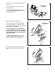
. Using a small plastic bag to keep your hand clean, apply some of the included grease to the axle on the right side of the Upright (2). 10 Identify the Right Upper Body Arm (9), which is marked with a “Right” sticker, and orient it as shown. Slide the Right Upper Body Arm onto the axle on the right side of the Upright (2). 8 Attach the Right Upper Body Arm (9) with an M8 x 20mm Patch Screw (80) and an M8 Washer (33). Repeat this step to attach the Left Upper Body Arm (8). Grease 33 2 11.
12. Have a second person hold a Bushing Cover (102) over the post on the right Upper Body Leg (6). Make sure that the curved side of the Bushing Cover is facing the Upper Body Leg. 12 Attach the Right Link Arm (98) and the Bushing Cover (102) to the right Upper Body Leg (6) with an M8 x 18mm Patch Hex Screw (85) and an M8 Washer (33). Then, press a Link Arm Screw Cover (104) onto the M8 x 18mm Patch Hex Screw (85). 6 Post Curved Side Repeat this step on the other side of the elliptical.
14. See the inset drawing. Identify a Pivot Cover A (19), which has hooks, and a Pivot Cover B (22), which has tabs. 14 Press a Pivot Cover A (19) and a Pivot Cover B (22) together around the Right Upper Body Arm (9). Repeat this step on the other side of the elliptical. Make sure that the Pivot Covers (19, 22) are positioned as shown. 22 Tabs Hooks 8 22 19 Hooks Orient the Front Upright Cover (16) so that the indicated arrow is pointing upward. 9 22 19 15.
16. Identify the Right Pedal (13), which is marked with a “Right” sticker. Attach the Right Pedal (13) to the Right Pedal Arm (49) with three M10 x 48mm Patch Screws (75) and three M10 Split Washers (78). Make sure to use the center hole and the two outer holes to attach the Right Pedal. 16 13 Attach the Left Pedal (not shown) to the Left Pedal Arm (not shown) in the same way. 78 17. Press the Rear Shield Cover (59) onto the Left and Right Shields (44, 45). 17 49 75 44 45 59 18.
HOW TO USE THE ELLIPTICAL HOW TO MOVE THE ELLIPTICAL HOW TO CHANGE THE INCLINE OF THE RAMP Due to the size and weight of the elliptical, moving it requires two persons. Stand in front of the elliptical, hold the upright, and place one foot against one of the front wheels. Pull on the upright and have a second person lift the handle until the elliptical will roll on the wheels. Carefully move the elliptical to the desired location, and then lower it to the floor.
HOW TO EXERCISE ON THE ELLIPTICAL To mount the elliptical, hold the handlebars or the upper body arms and step onto the pedal that is in the lowest position. Then, step onto the other pedal. Upper Body Arms Push the pedals until they begin to move with a continuous motion. Note: The pedal discs can turn in either direction. It is recommended that you turn the pedal discs in the direction shown by the arrow; however, for variety, you can turn the pedal discs in the opposite direction.
CONSOLE DIAGRAM Workouts Button Volume Buttons Display Button Resistance Buttons FEATURES OF THE CONSOLE For example, lose unwanted pounds with the 8-week Weight Loss workout. iFit workouts control the resistance of the pedals while the voice of a personal trainer coaches you through your workouts. iFit cards are available separately. To purchase iFit cards, go to www.iFit.com or see the front cover of this manual. iFit cards are also available at select stores.
HOW TO USE THE MANUAL MODE The display can show the following workout information: 1. Begin pedaling or press any button on the console to turn on the console. Time—When the manual mode is selected, this display will show the elapsed time. When a workout is selected, the display will show the time remaining in the workout instead of the elapsed time. When you turn on the console, the display will light. The console will then be ready for use. 2. Select the manual mode.
5. Measure your heart rate if desired. HOW TO USE A PRESET WORKOUT If there are sheets of plastic Contacts on the metal contacts on the handgrip pulse sensor, remove the plastic. To measure your heart rate, hold the handgrip pulse sensor with your palms resting against the metal contacts. Avoid moving your hands or gripping the contacts tightly. 1. Begin pedaling or press any button on the console to turn on the console. When you turn on the console, the display will light.
HOW TO USE AN IFIT WORKOUT If a different resistance level and/or target speed is programmed for the next segment, the resistance level and/or the target speed will flash in the display for a few seconds to alert you. The resistance of the pedals will then change. iFit cards are available separately. To purchase iFit cards, go to www.iFit.com or see the front cover of this manual. iFit cards are also available at select stores. 1. Begin pedaling or press any button on the console to turn on the console.
HOW TO USE THE SOUND SYSTEM An X will appear next to the currently selected backlight option. To change the backlight option, press the resistance increase and decrease buttons. To play music or audio books through the console sound system while you exercise, plug the included audio cable into the jack on the console and into a jack on your MP3 player or CD player; make sure that the audio cable is fully plugged in. Next, press the play button on your MP3 player or CD player.
MAINTENANCE AND TROUBLESHOOTING Inspect and tighten all parts of the elliptical regularly. Replace any worn parts immediately. Remove the M4 x 16mm Screws (92) from the Left Shield (44). Then, gently raise the front of the Left Shield and slide the rear of the Left Shield outward over the Left Pedal Arm (14). To clean the elliptical, use a damp cloth and a small amount of mild soap. IMPORTANT: To avoid damage to the console, keep liquids away from the console and keep the console out of direct sunlight.
HOW TO ADJUST THE REED SWITCH Locate the Reed Switch (58). Loosen, but do not remove, the M4 x 16mm Screw (92). If the console does not display correct feedback, the reed switch should be adjusted. To adjust the reed switch, you must remove the right disc cover and the right pedal disc. Using a flat screwdriver, remove the right Disc Cover (18). 24 27 92 81 58 41 18 24 Next, rotate the Crank Assembly (24) until a Magnet (41) is aligned with the Reed Switch (58).
EXERCISE GUIDELINES WARNING: Burning Fat—To burn fat effectively, you must exercise at a low intensity level for a sustained period of time. During the first few minutes of exercise, your body uses carbohydrate calories for energy. Only after the first few minutes of exercise does your body begin to use stored fat calories for energy. If your goal is to burn fat, adjust the intensity of your exercise until your heart rate is near the lowest number in your training zone.
PART LIST—Model No. PFEVEL74910.0 Key No. Qty. 1 2 3 4 5 6 7 8 9 10 11 12 13 14 15 16 17 18 19 20 21 22 23 24 25 26 27 28 29 30 31 32 33 34 35 36 37 38 39 40 41 42 43 44 45 46 47 48 49 50 1 1 1 1 1 2 1 1 1 2 2 1 1 1 2 1 8 2 2 1 1 2 1 1 1 1 1 2 4 2 1 1 8 1 1 1 1 2 1 1 2 1 7 1 1 1 2 2 1 2 Description Key No. Qty.
Key No. Qty. 101 102 103 104 105 106 107 108 109 110 2 2 2 2 4 2 2 1 1 1 Description Key No. Qty. Link Arm Bushing Bushing Cover Link Arm Cover Link Arm Screw Cover Bushing Set Ramp Axle Bushing Latch Spring Latch Latch Spacer Latch Pin 111 112 113 114 115 116 * * * 1 1 2 1 7 2 – – – Description Spring Bracket Latch Screw M10 Washer Latch Snap Ring M5 x 16mm Screw M10 x 70mm Button Bolt Userʼs Manual Assembly Tool Grease Packet Note: Specifications are subject to change without notice.
30 85 33 22 26 29 15 80 10 84 12 17 33 8 11 29 14 84 17 19 78 99 103 75 33 95 93 6 78 17 17 100 96 77 116 33 80 97 102 101 76 39 89 89 78 85 104 4 92 5 3 29 37 97 29 78 78 79 79 92 85 33 49 78 15 17 75 92 92 84 30 33 79 79 2 96 80 78 32 78 13 78 100 77 28 17 103 84 16 98 6 19 17 102 76 17 33 101 9 85 104 33 10 80 22 11 EXPLODED DRAWING A—Model No. PFEVEL74910.
18 26 18 41 92 46 92 41 92 27 47 92 48 70 92 82 24 91 44 43 79 113 50 51 91 115 47 92 48 58 59 57 40 92 90 52 34 56 7 87 43 91 86 83 36 54 71 35 91 77 55 91 38 115 7166 88 115 38 43 72 115 92 63 65 74 53 69 94 73 82 77 25 64 42 50 63 79 92 60 1 27 92 92 20 92 109 110 21 74 107 111 105 112 113 92 68 67 108 61 43 62 105 114 106 107 31 106 92 92 92 81 92 45 92 23 EXPLODED DRAWING B—Model No. PFEVEL74910.
ORDERING REPLACEMENT PARTS To order replacement parts, see the front cover of this manual.