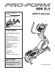
Model No. PFEVEL96010.0 Serial No. Write the serial number in the space above for reference. USERʼS MANUAL Serial Number Decal (on underside of frame) QUESTIONS? If you have questions, or if there are missing parts, please contact us: UK Call: 08457 089 009 From Ireland: 053 92 36102 Website: www.iconsupport.eu E-mail: csuk@iconeurope.com Write: ICON Health & Fitness, Ltd. c/o HI Group PLC Express Way Whitwood, West Yorkshire WF10 5QJ UK AUSTRALIA Call: 1-800-237-173 E-mail: australiacc@iconfitness.
TABLE OF CONTENTS WARNING DECAL PLACEMENT . . . . . . . . . . . . . . . . . . . . . . . . . . . . . . . . . . . . . . . . . . . . . . . . . . . . . . . . . . . . . .2 IMPORTANT PRECAUTIONS . . . . . . . . . . . . . . . . . . . . . . . . . . . . . . . . . . . . . . . . . . . . . . . . . . . . . . . . . . . . . . . .3 BEFORE YOU BEGIN . . . . . . . . . . . . . . . . . . . . . . . . . . . . . . . . . . . . . . . . . . . . . . . . . . . . . . . . . . . . . . . . . . . . . .4 ASSEMBLY . . . . . . . . . . . . .
IMPORTANT PRECAUTIONS WARNING: To reduce the risk of serious injury, read all important precautions and instructions in this manual and all warnings on your elliptical before using your elliptical. ICON assumes no responsibility for personal injury or property damage sustained by or through the use of this product. 1. Before beginning any exercise program, consult your physician. This is especially important for persons over age 35 or persons with pre-existing health problems. 9.
BEFORE YOU BEGIN manual. To help us assist you, note the product model number and serial number before contacting us. The model number and the location of the serial number decal are shown on the front cover of this manual. Thank you for selecting the revolutionary PROFORM® 505 ZLE elliptical. The 505 ZLE elliptical provides an impressive selection of features designed to make your workouts at home more effective and enjoyable. For your benefit, read this manual carefully before you use the elliptical.
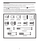
ASSEMBLY Assembly requires two persons. Place all parts of the elliptical in a cleared area and remove the packing materials. Do not dispose of the packing materials until assembly is completed. In addition to the included tool(s), assembly requires a Phillips screwdriver wrench , and a rubber mallet . , an adjustable See the drawings below to identify the small parts needed for assembly.
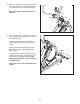
1. 1 To make assembly easier, read the information on page 5 before you begin. Attach the Front Stabilizer (6) to the Frame (1) with two M8 x 80mm Patch Screws (84). 6 84 1 2. Orient the Ramp (3) as shown. Then, insert the Ramp into the Frame (1). 2 Attach the Ramp (3) with five M8 x 19mm Patch Screws (82) and five M8 Split Washers (83). 3 3. Have a second person hold the Upright (4) near the Frame (1). 83 82 1 83 83 82 82 3 See the inset drawing.
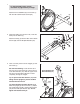
4. Apply a small amount of the included grease to the right Crank Arm (20) and to a 19mm Wave Washer (66). 4 Orient a Crank Arm Spacer (55) so that the flat end is facing away from the elliptical. Slide the Crank Arm Spacer and the 19mm Wave Washer (66) onto the right Crank Arm (20). 20 55 Flat End Identify the Right Roller Arm (59), which is marked with a “Right” sticker, and orient it as shown. Slide the Right Roller Arm (59) onto the right Crank Arm (20).
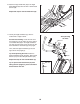
6. Identify the Right Upper Body Arm (61) and the Right Upper Body Leg (60), which are marked with “Right” stickers, and orient them as shown. Make sure that the hexagonal holes are in the indicated location. 6 61 Slide the Right Upper Body Arm (61) onto the Right Upper Body Leg (60). 102 Attach the Right Upper Body Arm (61) with two M8 x 38mm Bolts (96) and two M8 Locknuts (102). Make sure that the Locknuts are in the hexagonal holes.
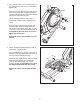
8. Attach an Outer Arm Cover (67) and the Inner Arm Cover (68) around the Right Upper Body Leg (60) with two M4 x 16mm Screws (104). 8 Repeat this step for the other side of the elliptical. 104 104 68 9. Apply a small amount of grease to the axle on the Right Upper Body Leg (60) and to a 19mm Wave Washer (66). 60 67 9 Identify the Right Pedal Arm (58), which is marked with a “Right” sticker, and orient it as shown.
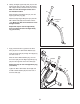
. Attach the Right Pedal Arm (58) to the Right Pedal Bracket (64) with two M10 x 45mm Patch Screws (99). 10 44 Repeat this step for the Left Pedal Arm (44). 64 58 99 11. Identify the Right Handlebar (9), which is marked with a “Right” sticker. See the inset drawing. Locate the wire tie in the Upright (4). Tie the lower end of the wire tie to the Pulse Wire (63) in the Right Handlebar (9). Next, pull the upper end of the wire tie until the Pulse Wire is routed through the Upright.
12. Attach the Water Bottle Holder (37) to the Upright (4) with two M4 x 16mm Screws (104). 12 4 104 104 37 13. Untie and discard the wire ties on the Wire Harness (111) and the Pulse Wires (63). While a second person holds the Console (7) near the Upright (4), connect the wires on the Console to the Wire Harness (111) and to the Pulse Wires (63). 13 Tip: Avoid pinching the wires. Attach the Console (7) to the Upright (4) with four M4 x 16mm Screws (104). 63 See step 3.
HOW TO USE THE CHEST PULSE SENSOR HOW TO PUT ON THE CHEST PULSE SENSOR the chest pulse sensor shuts off when it is removed and the electrode areas are dried. If the chest pulse sensor is not dried after each use, the battery may be drained prematurely. The chest pulse sensor has two components: a chest strap and a sensor unit (see the drawing below). Insert the tab on one end of the chest strap into one end of the sensor unit, as shown in the inset drawing.
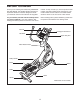
HOW TO USE THE ELLIPTICAL HOW TO PLUG IN THE POWER ADAPTER HOW TO MOVE THE ELLIPTICAL Due to the size and weight of the elliptical, moving it requires two persons. Stand in front of the elliptical, hold the upright, and place one foot against one of the front wheels. Pull on the upright and have a second person lift the handle on the ramp until the elliptical will roll on the front wheels. Carefully move the elliptical to the desired location, and then lower it to the floor.
HOW TO EXERCISE ON THE ELLIPTICAL HOW TO CHANGE THE INCLINE OF THE RAMP To mount the elliptical, hold the upper body arms and step onto the pedal that is in the lower position. Then, step onto the other pedal. Push the pedals until they begin to move with a continuous motion. Note: The crank arms can turn in either direction. It is recommended that you turn the crank arms in the direction shown by the arrow; however, for variety, you can turn the crank arms in the opposite direction.
CONSOLE DIAGRAM FEATURES OF THE CONSOLE For example, lose unwanted pounds with the 8-week Weight Loss workout. iFit workouts control the resistance of the pedals while the voice of a personal trainer coaches you through your workouts. iFit cards are available separately. To purchase iFit cards, go to www.iFit.com or see the front cover of this manual. iFit cards are also available at select stores.
HOW TO ACTIVATE THE CONSOLE 3. Change the resistance of the pedals as desired. The included power adapter must be used to operate the elliptical. See HOW TO PLUG IN THE POWER ADAPTER on page 13. When the power adapter is plugged in, the displays will light and the console will be ready for use. As you pedal, change the resistance of the pedals by pressing the Resistance increase and decrease buttons.
The upper display—This display can show the elapsed time, the distance that you have pedaled, your pedaling speed, and the approximate number of calories you have burned. When your pulse is detected, a flashing heart symbol will appear in the display, and then your heart rate will appear. For the most accurate heart rate reading, hold the contacts for at least 15 seconds. Note: If you continue to hold the handgrip pulse sensor, the display will show your heart rate for up to 30 seconds.
HOW TO USE A PRESET WORKOUT As you exercise, keep your pedaling speed near the target speed for the current segment. At the beginning of each segment, the target speed for the segment will flash in the display. 1. Begin pedaling or press any button on the console to turn on the console. See HOW TO ACTIVATE THE CONSOLE on page 16. 2. Select a preset workout.
HOW TO USE AN IFIT WORKOUT HOW TO USE THE SOUND SYSTEM iFit cards are available separately. To purchase iFit cards, go to www.iFit.com or see the front cover of this manual. iFit cards are also available at select stores. To play music or audio books through the console sound system while you exercise, plug the included audio cable into the jack on the console and into a jack on your MP3 player or CD player; make sure that the audio cable is fully plugged in. 1.
MAINTENANCE AND TROUBLESHOOTING Inspect and tighten all parts of the elliptical regularly. Replace any worn parts immediately. Locate and loosen the Idler Bolt (120). Next, tighten the Belt Adjustment Screw (88) until the Drive Belt (not shown) is tight. Then, retighten the Idler Bolt. To clean the elliptical, use a damp cloth and a small amount of mild soap. IMPORTANT: To avoid damage to the console, keep liquids away from the console and keep the console out of direct sunlight.
HOW TO ADJUST THE REED SWITCH Slide the Reed Switch (38) slightly closer to or away from the Magnet (43). Then, retighten the Reed Switch Screw. Turn the Pulley (19) for a moment. Repeat these actions until the console displays correct feedback. If the console does not display correct feedback, the reed switch should be adjusted. To adjust the reed switch, first use a flat screwdriver to rotate the left disc counterclockwise. Then, remove the left disc from the left disc mount.
EXERCISE GUIDELINES WARNING: Burning Fat—To burn fat effectively, you must exercise at a low intensity level for a sustained period of time. During the first few minutes of exercise, your body uses carbohydrate calories for energy. Only after the first few minutes of exercise does your body begin to use stored fat calories for energy. If your goal is to burn fat, adjust the intensity of your exercise until your heart rate is near the lowest number in your training zone.
PART LIST—Model No. PFEVEL96010.0 Key No. Qty. 1 2 3 4 5 6 7 8 9 10 11 12 13 14 15 16 17 18 19 20 21 22 23 24 25 26 27 28 29 30 31 32 33 34 35 36 37 38 39 40 41 42 43 44 45 46 47 48 49 50 1 1 1 1 3 1 1 1 1 1 1 1 1 1 4 1 1 1 1 2 8 1 1 1 1 1 1 1 1 4 1 2 1 2 1 4 1 1 1 6 2 4 2 1 1 1 1 1 1 1 Description Key No. Qty.
Key No. Qty. 101 102 103 104 105 106 107 108 109 110 111 112 113 2 6 1 16 2 2 4 10 1 4 1 1 1 Description Key No. Qty. M8 x 20mm Washer M8 Locknut Pivot Screw M4 x 16mm Screw Pedal Pad Motor Bracket Screw Roller Arm Bushing M6 x 13mm Screw Power Receptacle/Wire M8 x 16mm Patch Screw Wire Harness Power Adapter Drive Belt 114 115 116 117 118 119 120 121 122 * * * 2 1 1 2 2 1 1 1 1 – – – Description Foam Grip Right Pedal Right Pedal Insert Pulse Wire Upper Bushing M3.
EXPLODED DRAWING A—Model No. PFEVEL96010.
EXPLODED DRAWING B—Model No. PFEVEL96010.
EXPLODED DRAWING C—Model No. PFEVEL96010.
ORDERING REPLACEMENT PARTS To order replacement parts, see the front cover of this manual.