www.proform.com Model No. PFTL40012.0 Serial No. Write the serial number in the space above for reference. Serial Number Decal ACTIVATE YOUR WARRANTY To register your product and activate your warranty today, go to www.proformservice.com/ registration. CUSTOMER CARE For service at any time, go to www.proformservice.com. Or call 1-888-533-1333 Mon.–Fri. 6 a.m.–6 p.m. MT Sat. 8 a.m.–4 p.m. MT Please do not contact the store.
TABLE OF CONTENTS WARNING DECAL PLACEMENT . . . . . . . . . . . . . . . . . . . . . . . . . . . . . . . . . . . . . . . . . . . . . . . . . . . . . . . . . . . . . . .2 IMPORTANT PRECAUTIONS . . . . . . . . . . . . . . . . . . . . . . . . . . . . . . . . . . . . . . . . . . . . . . . . . . . . . . . . . . . . . . . . . . 3 BEFORE YOU BEGIN. . . . . . . . . . . . . . . . . . . . . . . . . . . . . . . . . . . . . . . . . . . . . . . . . . . . . . . . . . . . . . . . . . . . . . . .
IMPORTANT PRECAUTIONS WARNING: To reduce the risk of burns, fire, electric shock, or injury to persons, read all important precautions and instructions in this manual and all warnings on your treadmill before using your treadmill. ICON assumes no responsibility for personal injury or property damage sustained by or through the use of this product. 1. It is the responsibility of the owner to ensure that all users of this treadmill are adequately informed of all warnings and precautions. 12.
20. The heart rate monitor is not a medical device. Various factors, including the user’s movement, may affect the accuracy of heart rate readings. The heart rate monitor is intended only as an exercise aid in determining heart rate trends in general. 23. Never insert any object into any opening on the treadmill. 24. Inspect and properly tighten all parts of the treadmill regularly. 25. 21. Never leave the treadmill unattended while it is running.
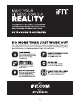
STANDARD SERVICE PLANS all 6
BEFORE YOU BEGIN Thank you for selecting the revolutionary PROFORM® BOSTON MARATHON® treadmill. The BOSTON MARATHON treadmill offers a selection of features designed to make your workouts at home more enjoyable and effective. Please see page 8 for a list of unique features of the BOSTON MARATHON treadmill. reading this manual, please see the front cover of this manual. To help us assist you, note the product model number and serial number before contacting us.
BOSTON MARATHON TREADMILL FEATURES adaptations. The impact absorption dramatically increases the comfort of the run so that you can run much longer and achieve the desired adaptation. This also reduces recovery time so that you can come back and train the next day. The BOSTON MARATHON® treadmill is a performance training tool for runners.
PART IDENTIFICATION CHART Use the drawings below to identify small parts used for assembly. The number in parentheses below each drawing is the key number of the part, from the PART LIST near the end of this manual. The number following the key number is the quantity used for assembly. Note: If a part is not in the hardware kit, check to see if it is preattached. Extra parts may be included.
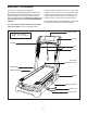
ASSEMBLY • Assembly requires three persons. • To identify small parts, see page 9. • Place all parts in a cleared area and remove the packing materials. Do not dispose of the packing materials until you finish all assembly steps. • Assembly requires the following tools: the included hex key • After shipping, there may be an oily substance on the exterior of the treadmill. This is normal. If there is an oily substance on the treadmill, wipe it off with a soft cloth and a mild, non-abrasive cleaner. 1.
2. Make sure that the power cord is unplugged. 2 Have two other persons hold the Uprights (116) near the brackets on the Base (104) as shown. Remove the tie securing the upright wire (A). 116 Connect the upright wire (A) to the base wire (B). See the inset drawing. The connectors should slide together easily and snap into place. If they do not, turn one connector and try again. IF YOU DO NOT CONNECT THE CONNECTORS PROPERLY, THE CONSOLE MAY BECOME DAMAGED WHEN YOU TURN ON THE POWER. B A A 104 3.
4. Insert the three tabs on the Tray (122) into the slots in the Console Back (123). 4 Attach the Tray (122) to the Console Back (123) with four #8 x 1" Screws (2) as shown. Start all four Screws, and then tighten them; do not overtighten the Screws. 123 122 2 2 2 5. See page 15. Plug in the power cord. 5 See page 17. Turn on the power. Then, touch the Quick Incline -6 button on the console. After the Frame stops moving, press the Quick Incline button numbered 20.
6. Identify the Right Inside Cover (120) and the Right Outside Cover (119). 6 Hold the Right Inside Cover (120) against the right Upright (116). Then, attach the Right Outside Cover (119) to the Right Inside Cover with three #8 x 1 1/2" Screws (1). Start all three Screws, and then tighten them. Attach the Left Inside Cover (not shown) and the Left Outside Cover (not shown) in the same way. 116 72 1 120 119 7.
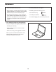
THE CHEST HEART RATE MONITOR HOW TO PUT ON THE HEART RATE MONITOR The heart rate monitor consists of a chest strap and a sensor. Insert the tab on one end of the chest strap into the hole in one end of the sensor as shown. Then, press the end of the sensor under the buckle on the chest strap. The tab should be flush with the front of the sensor. Tabs Chest Strap Sensor Tab Sensor Buckle The heart rate monitor must be worn under your clothes, tight against your skin.
OPERATION AND ADJUSTMENT HOW TO CONNECT THE POWER CORD nominal 120-volt circuit capable of carrying 15 or more amps. To avoid overloading the circuit, do not plug other electrical devices, except for lowpower devices such as cell phone chargers, into the surge suppressor or into an outlet on the same circuit. IMPORTANT: The treadmill is not compatible with GFCI-equipped outlets and may not be compatible with AFCI-equipped outlets.
CONSOLE DIAGRAM MAKE YOUR FITNESS GOALS A REALITY WITH IFIT.COM FEATURES OF THE CONSOLE The advanced treadmill console offers an array of features designed to make your workouts more effective and enjoyable. With your new iFit-compatible fitness equipment, you can use an array of features on iFit.com to make your fitness goals a reality: When you use the manual mode, you can change the speed and incline of the treadmill with the touch of a button.
HOW TO TURN ON THE POWER HOW TO USE THE TOUCH SCREEN IMPORTANT: If the treadmill has been exposed to cold temperatures, allow it to warm to room temperature before turning on the power. If you do not do this, you may damage the console displays or other electrical components. The console features a tablet with a full-color touch screen. The following information will help you become familiar with the tablet’s advanced technology: Plug in the power cord (see page 15).
HOW TO SET UP THE CONSOLE The console is now ready for you to begin working out. The following pages explain the various workouts and other features that the console offers. Before using the treadmill for the first time, set up the console. To use the manual mode, see page 19. To use the speed ring, see page 21. To use an onboard workout, see page 22. To use a set-a-goal workout, see page 23. To use an iFit workout, see page 24. 1. Connect to your wireless network.
HOW TO USE THE MANUAL MODE 4. Change the incline of the treadmill as desired. 1. Insert the key into the console. To change the incline of the treadmill, press the Incline increase and decrease buttons or one of the numbered Quick Incline buttons. Each time you press one of the buttons, the incline will gradually change until it reaches the selected incline setting. See HOW TO TURN ON THE POWER on page 17. Note: It may take a minute for the console to be ready for use. 2. Select the main menu.
• A track representing 1/4 mile (400 m) Press the fan increase button to increase the fan speed. If you press the fan increase button once while the fan is on its maximum speed setting, the auto fan mode will be selected. Press the fan decrease button repeatedly to decrease the fan speed or to turn off the fan. • Your pace in minutes per mile • Your current lap number • Your heart rate (see step 6) If desired, adjust the volume by pressing the volume increase and decrease buttons on the console. 8.
HOW TO USE THE SPEED RING 4. Press the cover back into place. Then, press a button on the speed ring to connect it to the console. The innovative speed ring functions like the Speed increase and decrease buttons on the console, except that it cannot be used to start the manual mode or a workout. Simply slide the speed ring onto your right or left index finger as shown. Note: Two straps of different lengths are included. Use the strap that fits the best.
HOW TO USE AN ONBOARD WORKOUT screen. After you view the workout summary, touch the Finish button to return to the main menu. You may also be able to either save or publish your results using one of the options on the screen. 1. Insert the key into the console. See HOW TO TURN ON THE POWER on page 17. If the speed and/or incline settings are too high or too low at any time during the workout, you can override the settings by pressing the Speed or Incline buttons.
HOW TO USE A SET-A-GOAL WORKOUT The workout will function in the same way as the manual mode (see pages 19 and 20). 1. Insert the key into the console. The workout will continue until you reach the goal that you set. The walking belt will then slow to a stop, and a workout summary will appear on the screen. After you view the workout summary, touch the Finish button to return to the main menu. You may also be able to either save or publish your results using one of the options on the screen.
HOW TO USE AN IFIT WORKOUT For more information about the iFit workouts, please see www.iFit.com. Note: To use an iFit workout, you must have access to a wireless network (see HOW TO USE THE WIRELESS NETWORK MODE on page 28). An iFit account is also required. When you select an iFit workout, the screen will show the name, duration, and distance of the workout. The screen will also show the approximate number of calories you will burn during the workout.
HOW TO USE THE EQUIPMENT SETTINGS MODE 7. Turn on or turn off the display demo mode. 1. Select the settings main menu. The console features a display demo mode, designed to be used if the treadmill is displayed in a store. While the demo mode is turned on, the console will function normally when you plug in the power cord, press the power switch into the reset position, and insert the key into the console. However, when you remove the key, the screen will show a demo presentation.
12. Set a safety screen timeout. Next, press the play button on your MP3 player, CD player, or other personal audio player. Then, adjust the volume level on your personal audio player or press the volume increase and decrease buttons on the console. The console features an automatic screen reset; if no buttons are touched or pressed and the walking belt does not move for a set amount of time, the console will automatically reset.
HOW TO USE THE MAINTENANCE MODE Note: Occasionally, a firmware update may cause your console to function slightly differently. These updates are always designed to improve your exercise experience. 1. Select the settings main menu. See step 1 on page 25. 4. Calibrate the incline system of the treadmill. 2. Select the maintenance mode. Touch the Calibrate Incline button. Then, touch the Begin button to calibrate the incline system.
HOW TO USE THE WIRELESS NETWORK MODE An information box will ask if you want to connect to the wireless network. Touch the Connect button to connect to the network or touch the Cancel button to return to the list of networks. If the network has a password, touch the password entry box. A keyboard will appear on the screen. To view the password as you type it, touch the Show Password checkbox. The console features a wireless network mode that allows you to set up a wireless network connection. 1.
HOW TO ADJUST THE CUSHIONING SYSTEM To decrease the firmness, step off the treadmill and turn the cushion adjustor handle clockwise until the handle is facing the back of the treadmill. Remove the key from the console and unplug the power cord. The treadmill features a cushioning system that reduces the impact as you walk or run on the treadmill. To learn more about the runner’s flex cushion, see page 8.
TROUBLESHOOTING SYMPTOM: The console displays remain lit when you remove the key from the console Most treadmill problems can be solved by following the simple steps below. Find the symptom that applies, and follow the steps listed. If further assistance is needed after you follow the steps, see the front cover of this manual. a. The console features a display demo mode, designed to be used if the treadmill is displayed in a store.
SYMPTOM: The walking belt slows when walked on SYMPTOM: The walking belt is off-center or slips when walked on a. Use only a surge suppressor that meets all of the specifications described on page 15. a. If the walking belt is off-center, first adjust the incline to 20 percent. Remove the key and UNPLUG THE POWER CORD.
EXERCISE GUIDELINES Burning Fat—To burn fat effectively, you must exercise at a low intensity level for a sustained period of time. During the first few minutes of exercise, your body uses carbohydrate calories for energy. Only after the first few minutes of exercise does your body begin to use stored fat calories for energy. If your goal is to burn fat, adjust the intensity of your exercise until your heart rate is near the lowest number in your training zone.
PART LIST Key No. Qty. 1 2 3 4 5 6 7 8 9 10 11 12 13 14 15 16 17 18 19 20 21 22 23 24 25 26 27 28 29 30 31 32 33 34 35 36 37 38 39 40 41 42 43 44 45 46 47 48 49 50 6 4 4 8 8 6 8 6 18 49 4 4 4 21 4 1 2 1 3 4 8 4 2 13 2 8 2 2 4 2 6 2 2 4 6 1 3 5 4 19 2 2 1 1 1 1 1 1 1 1 Model No. PFTL40012.0 R0413A Description Key No. Qty.
Key No. Qty. 101 102 103 104 105 106 107 108 109 110 111 112 113 114 115 116 1 1 1 1 2 2 2 1 1 1 1 1 1 1 2 1 Description Key No. Qty.
60 40 26 43 44 22 27 47 35 48 26 40 27 46 40 59 45 42 10 41 50 20 40 49 40 10 10 14 26 26 58 14 22 10 17 13 51 40 14 10 40 57 26 40 40 14 10 40 40 40 26 22 40 17 40 10 41 42 10 40 10 52 14 10 26 40 23 55 53 10 56 10 13 26 24 54 10 23 10 51 22 131 10 10 EXPLODED DRAWING A Model No. PFTL40012.
24 10 36 83 20 86 87 88 10 61 32 80 24 31 89 10 81 16 90 71 10 24 85 32 71 24 83 31 36 24 82 24 25 66 20 10 65 64 31 24 70 10 31 31 24 84 10 39 34 62 63 76 75 79 74 10 81 33 38 10 80 39 34 3 19 67 69 68 67 10 78 39 34 67 69 68 67 37 67 69 68 67 77 71 3 33 73 10 20 76 14 10 74 14 62 72 38 75 14 71 39 34 10 EXPLODED DRAWING B Model No. PFTL40012.
106 10 29 11 92 10 10 105 10 12 11 11 10 11 91 10 10 105 12 18 30 35 94 29 106 35 101 38 28 104 100 37 97 95 19 10 35 102 35 38 35 97 97 97 96 37 99 30 98 19 94 10 35 38 97 97 103 100 28 95 EXPLODED DRAWING C Model No. PFTL40012.
EXPLODED DRAWING D 7 108 8 107 Model No. PFTL40012.
EXPLODED DRAWING E Model No. PFTL40012.
ORDERING REPLACEMENT PARTS To order replacement parts, please see the front cover of this manual.