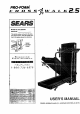
PRO.FORM" L K ..5 S ARS Model No. 831.297380 Serial No. The serialnumber is foundin the location shownbelow. Write the serial number in the space above for reference. Serial ,lumber Decal E_X EOU F=" R C I PH i S t=:=" ENT HELPLINE! 1-800-735-5879 • . ._:: ... _ ::xl .x • .-..w :_:_. structlon m this manua before ,_g thl equ=gment. Savethls manual _ ' future reference,_,," _ USER'S MANUAL SEARS, ROEBUCK AND Co.
TABLE OF CONTENTS IMPORTANT PRECAUTIONS .............................................. . .......... ..,,2 .1°.4 ASSEMBLY .......................................................... OPERATION AND ADJUSTMENT ........................................ HOW TO FoLD AND MOVE THE TREADMILL .............................. TROUBLE-SHOOTING ................................................. CONDITIONING GUIDELINES ........................................... ORDERING REPLACEMENT PARTS o,..,.,o=oo .. • . , .. .....
The decal shown at the right has been placed on your treadmill. If the decal Is missing, or if it is not legible, please call our toll-free HELPLINE to order a free replacement decal (see the back cover of thls manual). Apply the decal In the location shown. • J,WARNING! • Never allow children to play on Or around treadm,ll. . • Storage latch must be fully en.qaged before treadmill is moved or stored.
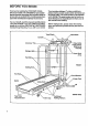
BEFORE YOU BEGIN Thank you for selecting the PROFORM* CROSSWALK 2.5 treadmill. The CROSSWALK 2.5 treadmill blends advanced technology with innovative design to let you enjoy an excellent form of cardiovascular exercise in the convenience and privacy of your home. For your benefit, read this manual carefully before using the treadmill. If you have additional questions, please cell our toll-free HELPUNE at 1-800-736-6879, Monday through Saturday, 7 a.m. until 7 p.m. Central Time (excluding holidays).
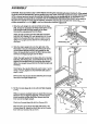
ASSEMBLY CAUTION: Read and follow step I below before removing the restraining tie (see drawing 1). If the restrainIng tie is removed prematurely, sedous bodlly Injury may resulL Assembly requires two people. Set the treadmill in a cleared area and remove the packing materials except for the restraining tie. Do not dispose of the packing materials until assembly is completed. Usa the HARDWARE IDENTIRCATION CHART in the center of this manual to identify the pads used in assembly.
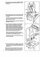
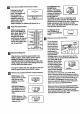
4, Withthe helpof a secondperson,carefullylowertheLeft and Right Uprights (1,44) until the handraits are resting on the floor. 59 Attach six Base Pads (57) to the bottom of the Base (59) in the indicated locations. Note: An extra Base Pad may be included. 5, 3 See drawing 4 above. With the help of a second person, raise the Left and Right Uprights (1,44) until the Base (59) is resting flat on the floor. Before moving the treadmill, see HOW TO MOVE THE TREADMILL on page 11. 59 .
OPERATION AND ADJUSTMENT THE PERFORMANT LUBE TM WALKING BELT Your treadmill features a walldng belt coated with PERFORMANT LUBE TM, a high-performance lubdcent. IMPORTANT: Never apply silicone spray or other substances to the walking belt or the walking platform. They will detadorate the walking belt and cause excessive wear. electric shock. This product is equipped with a cord having an equipment-grounding conductor and a grounding plug.
DIAGRAM OF THE CONS0"LE BATI'ERY INSTALLATION STEP BY STEP CONsoLE The console requires three "AA" batteries (not Included). Alkaline batteries are recommended. Before operating the console, make sure that the power cord Is properly plugged In. (See HOW TO PLUG IN THE POWER CORD on page 7.) If there is a thin sheet of clear plastic on the face of the console_ remove it. To install battedes, open the battew cover under the console as shown below. Press three batteries Into the batte_j comp_tment.
D Insert the key fully into the power switch. ORIES/PULSE display--This display shows the approximate CALORIES/FAT CALI Arro_ GALS. / FATC4L_ numbers of calories and fat calories you have burned. (See FAT CALORIES on page 14 for an eXplanation of fat c_odas.) Every seven seconds, the display will change from one number to the other. Arrows in the display will indicate which number is currently shown. Note: This display wtll also show your pulse when the pulse sensor is used.
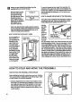
r_ when you are finished'exercising, walking belt and remove the key. step the Step onto the foot rails, stop the walking belt, and remove the key from the console. Store HOW TO CHANGE THE INCLINE OF THE TREADMILL the key in a eecure place. After the key is removed, the displays will remain on for about five minutes. The Incline of the treadmill can'be changed by raLslngor lowering the back end. BefOre changing the Incline, remove the key and unplug the power cord.
2.Moveyourdghthandtothepositionshownandholdthe treadmillfirmly.Raisethetreadmilluntilthe storage latch closes over the frame guide. Make sure that the storage latch closes fully over the frame guide. To protect the floor or carpet from damage, place e mat under the treadmill.
TROUBLE-SHOOTING Most treadmill problems can be solved by following the simple steps below. Find the symptom that applies, and follow the steps listed. If further assistance Is needed, call our toll-free HELPLINE at 1-800-7366879, Monday through Saturday, 7 a.m. until 7 p.m. Central Time (excluding holidays). 1. SYMPTOM: THE POWER DOES NOT TURN ON a. Make sure that the power cord is plugged into a surge protector, and that the surge protector is plugged into a propedy grounded outlet.
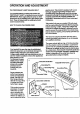
6.SYMPTOM: THEWALKINGBELTISOFF-CENTER WHENWALKEDON a. If thewalkingbelthasshiftedtotheleft,firstremove the key and UNPLUG THE POWER CORD. Using the 3/16" end of the allen wrench, tum the left rear roller adjustment bolt clockwise, and the dght bolt countemlockwise, 1/4 of a tum each. Be careful not to overtighten the walking belt. Plug in the power cord, insert the key and run the treadmill for a few minutes. Repeat until the walking belt is centered. b.
Locate the Reed Switch (38) and the Magnet (39) on the left side of the Pulley (90). Turn the Pulley until the Magnet is aligned with the Reed Switch. Make sure that the gap between the Magnet and the Reed Switch Is about 1/8". If necessary, loosen,the Screw (19) and move the Reed Switch slightly. Retighten the Screw. Re-attach the hood (see 8. b. on page 13), and run the treadmill for a few minutes to check for a correct speed reading. 1/8"- -- 38-|J 19f____. Top View .
High PerformanceAthleticConditioning Training Zone Exercise if yourgoalis highperformance athleticconditioning, set _e speed control on the console to PERFORMANCE to help you maintain the proper intensity level. (See page 9.) Note: During the first few weeks of your exercise program, keep your heart rate near the low end of your training zone. After warming up, increase the Intensity of your exercise until your heart rate is in your training zone for 20 to 60 minutes.
Remove this HARDWARE IDENTIFICATION CHART, EXPLODED DRAWING and PART LIST from the user's manual. Save this page for future reference. HARDWARE IDENTIFICATION CHART The chart below is provided to help you identify the small parts used in assembly. The number in parenthesis below each part refers to the key number of the part. The second number refers to the quantity used in assembly. Note: Some small parts may have been pre-assembled for shipping purposes.
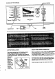
EXPLODED DRAWINGmModel NO. 831.297380 Ro197A 82 62 92 \ 66 75 75 51 98 67 63 22 103 70 106 102 107 5 ÷- 97 81 ~*- 77 93 .J 68 °f .27 4 47 72 91 67 J 74 66 78 6 `/ 70 74 "_.
6 \ 36 19 37, 2O i! 124 25 I 38 28 111 28 27 97 98 r 99 84 5 67 48 103 °° 3O 6O 104 105 47 108 46 114 }g_.
PART LIST--Model Key No. Part No. Qty. 1 2 3 4 5 6 7 8 9 10" 11 12 13 14 15 16 17 18 19 20 21 22 23 24 25 26 27 28 29 30 31" 32 33 34* 35 36 37 38 39 40 41 42 43 44 45 46 47 48 49 50 51 52 53 54 55 56 57 58 , 59 60 61 62 63 135635 131882 113227 136012 128005 119425 131161 128113 131606 133961 119038 126134 124669 122812 014117 012055 120867 135194 120630 107503 130993 013307 NSP 013300 133964 133860 133333 113106 013322 109382 124695 130426 135530 133966 .
8E /41 6 The model number and sedal number of your PROFORM • CROSSWALK 2.5 treadmill are listed on a decal attached to the frame. See the front cover of this manual to find the location of the decal. Model No. 831.