Model No. 831.24855.0 Serial No. Write the serial number in the space above for reference. TREADMILL EXERCISER User's Manual Serial Number Decal • Assembly • Operation • Maintenance • Part List and Drawing Sears, Roebuck and Co.
TABLE OF CONTENTS WARNING DECAL PLACEMENT .............................................................. IMPORTANT PRECAUTIONS ................................................................ BEFORE YOU BEGIN ...................................................................... ASSEMBLY ............................................................................... OPERATION AND ADJUSTMENT ............................................................ HOW TO FOLD AND MOVE THE TREADMILL ......................
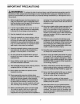
IMPORTANT PRECAUTIONS 3
BEFORE YOU BEGIN Thank you for selecting the revolutionary PROFORM ® XP TRAINER 580 treadmill. The XP TRAINER 580 treadmill offers an impressive selection of features designed to make your workouts at home more enjoyable and effective. And when you're not exercising, the unique XP TRAINER 580 treadmill can be folded up, requiring less than half the floor space of other treadmills. ing this manual, please see the back cover of this manual.
ASSEMBLY Assembly requires two persons. Set the treadmill in a cleared area and remove all packing materials. Do not dispose of the packing materials until assembly is completed. Note: The underside of the treadmill walking belt is coated with high-performance lubricant. During shipping, a small amount of lubricant may be transferred to the top of the walking belt or the shipping carton. This is a normal condition and does not affect treadmill performance.
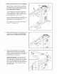
1. Make sure that the power cord is unplugged. 87 Hole With the help of a second person, carefully tip the treadmill onto its left side. Partially fold the Frame (51) so that the treadmill is more stable; do not fully fold the Frame yet. 79 84 Cut the shipping tie securing the Upright Wire (79) to the Base (87). Locate the plastic tie in the indicated hole in the Base, and use the tie to pull the Upright Wire out of the hole.
4, Hold a Bolt Spacer (81) inside the lower end of the Right Upright (80). Insert a 3/8" x 4" Bolt (9) with a 3/8" Star Washer (12) into the Right Upright and the Bolt Spacer. Repeat this step with a second Bolt Spacer (81), 3/8" x 4" Bolt (9), and 3/8" Star Washer (12). 9 i-i Hold the Right Upright Spacer (82) and the Right Upright (80) against the Base (87). Be careful not to pinch the Upright Wire (79).
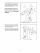
6, Hold a Bolt Spacer (81) inside the lower end of the Left Upright (75). Insert a 3/8" x 4" Bolt (9) with a 3/8" Star Washer (12) into the Left Upright and the Bolt Spacer. Repeat this step with a second Bolt Spacer (81), 3/8" x 4" Bolt (9), and 3/8" Star Washer (12). 6 75 Hold the Left Upright Spacer (86) and the Left Upright (75) against the Base (87). Tighten the 3/8" x 4" Bolts (9) until the heads of the Bolts touch the Upright; do not fully tighten the Bolts yet.
9, Attach the Left Handrail (107) and the Right Handrail (104) with six 5/16" x 1" Bolts (6) and four 5/16" Star Washers (13) as shown. Do not fully tighten the Bolts yet. Slide the Handrail Caps (105) away from the Uprights (75, 80). Attach the lower end of each Handrail (104, 107) to the Uprights with a #10 x 3/4" Screw (5). Orient the Handrail Caps (105) as shown. Secure a Handrail Cap to each Handrail (104, 107) with a #8 x 1/2" Screw (2). 10.
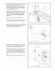
. Attach the Crossbar (106) to the Left and Right Handrails (107, 104) with two 1/4" x 3/4" Bolts (10) with two 1/4" Star Washers (14) into the Crossbar. Start both Bolts but do not tighten them yet. 11 106 12. Have a second person hold the console assembly near the Right Handrail (104) and Left Handrail (not shown). Connect the Upright Wire (79) to the console wire. See the inset drawing. The connectors should slide together easily and snap into place. If they do not, turn one connector and try again.
14. Attach the console assembly to the Left and Right Handrails (107, 104) and the Crossbar (106) with four #8 x 3/4" Screws (1) and four #8 x 1/2" Screws (2). Start all eight Screws before tightening them. 14 Console Assembly 107 Tighten the six 5/16" x 1" Bolts (6) (only three are shown). Tighten the two 1/4" x 3/4" Bolts (10) (only one is shown). See assembly steps 4 and 6. Firmly tighten the four 3/8" x 4" Bolts (9). 15.
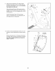
16. Raise the Frame (51) to the position shown. Have a second person hold the Frame until this step is completed. 16 Orient the Storage Latch (48) so that the large barrel and the Latch Knob (49) are oriented as shown. Attach the upper end of the Storage Latch (48) to the bracket on the Frame (51) with a 3/8" x 2" Bolt (7) and a 3/8" Nut (11). Attach the lower end of the Storage Latch (48) to the Base (87) with a 3/8" x 1 3/4" Bolt (8).
OPERATION AND ADJUSTMENT THE PRE-LUBRICATED WALKING BELT tric shock. This product is equipped with a cord having an equipment-grounding conductor and a grounding plug. Plug the power cord into a surge suppressor, and plug the surge suppressor into an appropriate outlet that is properly installed and grounded in accordance with all local codes and ordinances. Your treadmill features a walking belt coated with highperformance lubricant.
CONSOLE DIAGRAM TIME 5 M_H OO \ \ \ \ 6 STOP \ \ } } } FEATURES OF THE CONSOLE To turn on the power, see page 16. To use the manual mode, see page 16. To use a preset workout, see page 18. To use the information mode, see page 19. To use the stereo sound system, see page 19. The treadmill console offers an impressive array of features designed to make your workouts more effective and enjoyable.
HOW TO TURN ON THE POWER HOW TO USE THE MANUAL MODE IMPORTANT: If the treadmill has been exposed to cold temperatures, allow it to warm to room temperature before turning on the power. If you do not do this, you may damage the console displays or other electrical components. 1. Plug in the power cord (see page 14). Next, locate the reset/off circuit breaker on the treadmill frame near the power cord. Switch the circuit breaker to the reset position. Insert the key into the console.
4. Change the incline of the treadmill as desired. To change the incline of the treadmill, press the Incline increase and decrease buttons or one of the numbered incline Speed display--This display shows the speed of the walking belt. r ' b.b SPEED L INOLINE To reset the displays, press the Stop button, remove the key, and then reinsert the key. buttons. Each time you press the incline increase or decrease button, the incline will change by 0.5%.
HOW TO USE A PRESET WORKOUT 1. segment, a series of tones will sound and the Current Segment next segment of the profile will begin to flash. If a different speed or incline setting is programmed for the next segment, the speed or incline setting will flash in the display to alert you. Insert the key into the console. See HOW TO TURN ON THE POWER on page 16. 2. Select a preset workout.
THE INFORMATION MODE HOW TO USE THE STEREO SOUND SYSTEM The console features an information mode that keeps track of the total number of hours that the treadmill has To play music or audio books through the console's stereo speakers, you must connect your MP3 player, CD player, or other personal audio player to the console through the audio jack. been used and the total distance that the walking belt has moved.
HOW TO FOLD AND MOVE THE TREADMILL HOW TO FOLD THE TREADMILL FOR STORAGE Before folding the treadmill, adjust the incline to the lowest position, If you do not do this, you may damage the treadmill when you fold it, Remove the key and unplug the power cord, CAUTION: You must be able to safely lift 45 Ibs, (20 kg) to raise, lower, or move the treadmill, 1. Hold the metal frame firmly in the location shown by the arrow at the right.
HOW TO LOWER THE TREADMILL FOR USE 1. Hold the upper end of the treadmill with your right hand. Pull the latch knob to the left and hold it. It may be necessary to push the frame forward as you pull the knob to the left. Pivot the frame downward and release the latch knob. Latch Knob 2. Hold the metal frame firmly with both hands and lower it to the floor. CAUTION: Do not grip only the plastic foot rails or drop the frame to the floor. Bend your legs and keep your back straight.
TROUBLESHOOTING Most treadmill problems can be solved by following the simple steps below. Find the symptom that applies, and follow the steps listed. If further assistance is needed, see the back cover of this manual. PROBLEM: The power does not turn on SOLUTION: a. Make sure that the power cord is plugged into a surge suppressor, and that the surge suppressor is plugged into a properly grounded outlet (see page 14).
Remove the three #8 x 3/4" Screws (1) and carefully pivot the Motor Hood (60) off. 6O Locate the Reed Switch (71) and the Magnet (45) on the left side of the Pulley (46). Turn the Pulley until the Magnet is aligned with the Reed Switch. Make sure that the gap between the Magnet and the Reed Switch is about 1/8 in. (3 mm). If necessary, loosen the 3/4" Screw (17), move the Reed Switch slightly, and then retighten the Screw.
PROBLEM: The walking belt is off-center or slips when walked on SOLUTION: a. If the walking belt is off-center, first remove the key and UNPLUG THE POWER CORD. If the walking belt has shifted to the left, use the hex key to turn the left idler roller bolt clockwise 1/2 of a turn; if the walking belt has shifted to the right, turn the bolt counterclockwise 1/2 of a turn. Be careful not to overtighten the walking belt. Then, plug in the power cord, insert the key, and run the treadmill for a few minutes.
EXERCISE GUIDELINES Burning Fat--To burn fat effectively, you must exercise at a low intensity level for a sustained period of time. During the first few minutes of exercise, your body uses carbohydrate calorieefor energy. Only after the first few minutes of exercise does your body begin to use stored fat ca/ofies for energy. If your goal is to burn fat, adjust the intensity of your exercise until your heart rate is near the lowest number in your training zone.
PART LISTmModel No. 831.24855.0 Ro808A To locate the parts listed below, see the EXPLODED DRAWING near the end of this manual. Key No. Qty. Description Key No. Qty.
Key No. Qty. 101 102 103 104 105 106 107 1 6 1 1 2 1 1 Description Key No. Qty. Key Plate Console Clamp Right Tray Right Handrail Handrail Cap Crossbar Left Handrail 108 2 - Description #8 x 1 1/2" Screw 8" Blue Wire, M/F 10" Blue Wire, 2F 12" Red Wire, M/F 10" Black Wire, M/F User's Manual Note: Specifications are subject to change without notice. See the back cover of this manual for information about ordering replacement parts. If a part is missing, call 1-888-533-1333.
EXPLODED DRAWING AmModel NO. 831.24855.
EXPLODED DRAWING B--Model No. 831.24855.
EXPLODED DRAWING CmModel NO. 831.24855.
EXPLODED DRAWING DmModel NO. 831.24855.
Your Home For repair--in or heating your home--of all major brand appliances, and cooling systems, no matter who made For the replacement parts, accessories, lawn and garden equipment, it, no matter who sold it! and user's manuals that you need to do-it-yourself. For Sears professional installation of home appliances and items like garage door openers and water heaters. 1-800-4-MY-HOME ® (1-800-469-4663) Call anytime, day or night (U.S.A. and Canada) www.sears.com www.sears.