
Specifications


10
Programming
The configuration and programming of
the S7-400 is based on STEP® 7.
STEP 7 offers functions for every phase
of an automation project – from config-
uration to startup, testing and servicing.
STEP 7
STEP 7 incorporates the SIMATIC Man-
ager, the central tool for the soft-
ware-related handling of the project.
This relates not only to a single CPU, but
to the whole plant – irrespective of how
many controllers, drives and HMI devic-
es the solution consists of. Using STEP 7
also ensures that the data is kept consis-
tent throughout the project.
STEP 7 incorporates both the hardware
configuration of the plant and the pa-
rameterization of the modules, so there
are no more hardware settings to be
made. STEP 7 also includes the three ba-
sic languages: statement list (STL), lad-
der diagram (LAD) and function block
diagram (FBD). STEP 7 also makes it pos-
sible to parameterize high-speed data
communications between networked
CPUs.
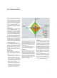
Engineering Tools
As the S7-400 is generally used for exe-
cuting large programs, there are also
higher-level languages and graphical
engineering tools based on STEP 7.
These have the additional functionality
to enable you to program automation
solutions in a function-oriented manner
and using a user-friendly interface.
The following tools are available for pro-
gramming:
S7-SCL
(Structured Control Language), PAS-
CAL-based higher-level language for
programming SIMATIC S7/C7 control-
lers
S7-GRAPH
enables graphical configuration of se-
quential control systems for SIMATIC
S7/C7
S7-HiGraph
®
for graphical description of sequential
or asynchronous process with status di-
agrams for SIMATIC S7/C7
CFC
(Continuous Function Chart), the tech-
nology-oriented diagram which enables
graphical interconnection of complex
functions for SIMATIC S7
Data storage
The new STEP 7 Version 5.1 allows any
data to be saved to the CPU, i.e. if you
are servicing or upgrading the system,
the personnel can still access not only
the programs running, but also the
whole project, including any comments
and symbols. If you are using high-
er-level languages or graphical engi-
neering tools, the program source code
is also immediately available in its origi-
nal form or in graphical format. Last but
not least, it is also possible to save cus-
tomer-specific operating instructions,
manuals and machine documentation
directly on the CPU in all standard file
formats.
Memory required for engineering tools
Memory requirement
Productivity