802.
FCC Warning This equipment has been tested and found to comply with the limits for a Class B digital device, pursuant to part 15 of the FCC Rules. These limits are designed to provide reasonable protection against harmful interference in a residential installation. This equipment generates, uses, and can radiate radio frequency energy and, if not installed and used in accordance with the instructions, may cause harmful interference to radio communication.
Copyright 2007 All Rights Reserved. No part of this document can be copied or reproduced in any form without written consent from the company. Trademarks: All trade names and trademarks are the properties of their respective companies. Revision History Revision History V1.
Table of Contents 1. Introduction ........................................................................6 1.1 Introduction .................................................................................................. 6 1.2 Product Features ......................................................................................... 6 2. Hardware Installation........................................................10 2.1 System Requirements .............................................................
6.2.4 DHCP Relay ........................................................................................ 45 6.2.5 DNS Relay........................................................................................... 46 6.3 Wireless....................................................................................................... 47 6.3.1 Access Point Settings ....................................................................... 47 6.3.2 Multiple SSIDs Settings ........................................
11. Troubleshooting ..............................................................79 11.1 Using LEDs to Diagnose Problems ........................................................ 79 11.1.1 Power LED...................................................................................... 79 11.1.2 LAN LED ......................................................................................... 79 11.1.3 ADSL LED....................................................................................... 79 11.
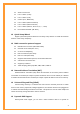
1. Introduction 1.1 Introduction This full rate Wireless ADSL2+ router is an all-in-one gateway for Home and SOHO applications. This gateway are with full-featured ADSL router that provides high-speed Internet access, 4-port Ethernet switch direct connections to individual PCs or local area network with 10/100 Base-T Ethernet and 54Mbps IEEE802.11g wireless connectivity. This device uses advanced ADSL chipset solution with complete set of industry standard features for high-speed Internet access.
z ANSI T1.413 issue 2 z ITU-T G.992.1 (G.dmt) z ITU-T G.992.2 (G.lite) z G.994.1 (G.hs, Multimode) z ITU-T G.992.3 (ADSL2 G.dmt.bis) z ITU-T G.992.4 (ADSL2 G.lite.bis) z ITU-T G.992.5 (ADSL2+; Annex A, B, I, J, L & M) z Reach Extended ADSL (RE ADSL) Quick Setup Wizard Support Quick Setup Wizard Web GUI and Easy setup software to install this Wireless ADSL2+ router easily and quickly.
address, allowing the host to be more easily accessible from various locations on the Internet. You must register for this service with a Dynamic DNS client. DHCP Support DHCP (Dynamic Host Configuration Protocol) allows individual clients to obtain TCP/IP configuration at start-up from a centralized DHCP server. The ADSL router has built-in DHCP server capability enabled by default. It can assign IP addresses, an IP default gateway and DNS servers to DHCP clients.
z Supports Quality of Service (QoS), 802.
2. Hardware Installation 2.1 System Requirements z Pentium III 266 MHz processor or higher z 128 MB RAM minimum z 20 MB of free disk space minimum z RJ45 Ethernet Port 2.2 Package Contents z Wireless ADSL2+ Router z RJ-45 Ethernet cable z RJ-11 Phone cable z Power Adapter z Quick Installation Guide z One External Antenna (for detachable model) 2.3 Front Panel Indicators and Description Front panel of this Wireless ADSL2+ router has LED indicators to display router’s operating status.
2.4 Back Panel PWR Connect with power adapter ON/OFF Power switch button LINE Connect with phone cable 4 Connect with Ethernet Cable to Switch Hub or PC 3 Connect with Ethernet Cable to Switch Hub or PC 2 Connect with Ethernet Cable to Switch Hub or PC 1 Connect with Ethernet Cable to Switch Hub or PC DEFAULT Reset button 2.
3. Connecting Wireless ADSL2+ Router via Ethernet Your router can be managed from anywhere with the embedded Web configuration using a Web browser, such as Microsoft Internet Explorer or Netscape Navigator. Internet Explorer 6.0 and later or Netscape Navigator 7.0 and later versions with JavaScript enabled should be used. 3.1 Setup Wireless ADSL2+ router via Ethernet Cable If there is an available LAN card present on your PC, you just simply connect ADSL router and PC through the Ethernet cable.
Option1: Get an IP from Router Automatically Select the IP Address tab. In this page, click Obtain an IP address automatically radio button.
2) Then, select DNS Configuration tab and select Disable DNS then click OK to finish the configuration. Option2: Configure IP Manually 1) At IP Address tab, select Specify an IP address, set default IP address for the Router is 192.168.1.1, so use 192.168.1.X (X is a number between 2 to 254) for IP Address field and 255.255.255.0 for Subnet Mask field.
2) Select Gateway tab and add default Router IP Address “192.168.1.1” in the New gateway field and click Add. Under DNS Configuration tab, select Enable DNS and add DNS values (192.168.1.1) in DNS Server Search Order field then click Add.
For Windows 2000 Step 1: (a) Right-click My Network Places and select Properties in the main window screen (b) Or, go to Start / Settings / Control Panel. In the Control Panel, double-click on Network and Dial-up Connections.
Step 3: Select Internet Protocol (TCP/IP) then click Properties: Configure IP Automatically: Step 4: Select Obtain an IP address automatically and Obtain DNS server address automatically then click OK to complete IP configuring process.
Configure IP Manually: Step 4: Select Use the following IP address and Use the following DNS server addresses. IP address: Fill in IP address 192.168.1.x (x is a number between 2 to 254). Subnet mask: Default value is 255.255.255.0. Default gateway: Default value is 192.168.1.1. Preferred DNS server: Fill in preferred DNS server IP address. Alternate DNS server: Fill in alternate DNS server IP address. For Windows XP Step 1: Click Start then select Control Panel.
Step 2: Double-click Network Connections icon.
Step 4: Select Internet Protocol (TCP/IP) then click Properties: Configure IP address Automatically: Step 5: Select Obtain an IP address automatically and Obtain DNS server address automatically. Click OK to finish the configuration.
Configure IP Address Manually: Step 5: Select Use the following IP address and Use the following DNS server addresses. IP address: Fill in IP address 192.168.1.x (x is a number between 2 to 254). Subnet mask: Default value is 255.255.255.0. Default gateway: Default value is 192.168.1.1. Preferred DNS server: Fill in preferred DNS server IP address. Alternate DNS server: Fill in alternate DNS server IP address.
For Windows Vista Step 1: Click Start then select Control Panel (in the Classic View). Step 2: Double-click Network and Sharing Center icon.
Step 3: Select “Manage Network connections”.
Step 5: Select Internet Protocol (TCP/IP) then click Properties: Configure IP address Automatically: Step 6: Select Obtain an IP address automatically and Obtain DNS server address automatically. Click OK to finish the configuration.
Configure IP Address Manually: Step 7: Select Use the following IP address and Use the following DNS server addresses. IP address: Fill in IP address 192.168.1.x (x is a number between 2 to 254). Subnet mask: Default value is 255.255.255.0. Default gateway: Default value is 192.168.1.1. Preferred DNS server: Fill in preferred DNS server IP address. Alternate DNS server: Fill in alternate DNS server IP address.
4. Configure Wireless ADSL2+ Router via HTML This device supports a Web-based (HTML) GUI to allow users to configure Router setting via Web browser. 4.1 Login 1) Launch the Web browser. 2) Enter the default IP address http://192.168.1.1 3) Entry of the username and password will be displayed. Enter the default login User Name and Password: z The default login User Name of the administrator is admin, and the default login password is admin.
4.2 Navigating the Web Configurator Steps to navigate the Web configuration from the Site Map are summarized as below. Steps to navigate the Web configuration from the Site Map are summarized below. ¾ Click on Quick Start to begin a wizard that helps to configure your router. ¾ Click on Interface Setup to configure Internet and LAN functions. ¾ Click on Advanced Setup to configure advanced features. ¾ Click on Access Management to manage Internet access options.
5. Quick Start Wizard Click Quick Start to guide you to configure the device to connect your ISP and have Internet access within minutes. This Quick Start will guide you step by step to configure the password, time zone, and WAN settings of you device. This Wizard is a helpful guide for first time uses to the device. NOTE: It is a strong recommendation that using Quick Start to configure your ADSL settings. Click on the RUN WIZARD button to start the Quick Start wizard.
. The Quick Start Setup Wizard includes four quick steps: 1) Set your new password. 2) Choose your time zone. 3) Set your Internet connection. 4) Re-start your ADSL router. Please follow the quick start step by step to configure the device. Note: If your ISP doesn’t provide DNS, after you complete Quick Start configuration, please go to Interface Setup Æ Internet to configure your DNS settings. Click on NEXT to continue, or on EXIT to exit the wizard without saving.
5.1 Setting a New Password This screen helps you set a new password, replacing the default password. The following table describes the labels in this screen. LABEL DESCRIPTION New Password Enter the password you wish to use here Confirmed Password Enter the password again to confirm Click on BACK to return to the previous screen, on NEXT to continue, or on EXIT to exit the wizard without saving. 5.2 Choose your Time Zone This screen helps you set the time zone for your ADSL2+ Router.
5.3 Set your Internet Connection This screen helps you select, then configure, your ISP connection type. Select the Internet connection type you use to connect to your ISP. Click on BACK to return to the previous screen, on NEXT to continue, or on EXIT to exit the wizard. The following screen will vary depending on which connection type you chose. Each screen is explained below: 5.3.
The following table describes the labels in this screen. LABEL DESCRIPTION VPI Enter the VPI here. VPI can range from 0 to 255. VCI Enter the VCI here. VCI can range from 1 to 65535. Connection Type Select your connection type from the dropdown list. Your ISP should provide the above information. Click on BACK to return to the previous screen, on NEXT to continue, or on EXIT to exit the wizard without saving. 5.3.
5.3.3 Configuring PPPoE PPPoE provides access control and billing functionality in a manner similar to dial-up services using PPP. The router bridges a PPP session over Ethernet (PPP over Ethernet, RFC 2516) from your computer to an ATM Permanent Virtual Circuit (PVC) that connects to the ADSL Access Concentrator, where the PPP session terminates. Single PVC can support any number of PPP sessions from your LAN. The following table describes the labels in this screen.
The following table describes the labels in this screen. LABEL DESCRIPTION Username Enter your username here. Password Enter your password here. VPI Enter the VPI here. VPI can range from 0 to 255. VCI Enter the VCI here. VCI can range from 1 to 65535. Connection Type Select your connection type from the dropdown list. Your ISP should provide the above information. Note that you must enter the user name exactly as your ISP assigned it.
The following table describes the labels in this screen. LABEL DESCRIPTION VPI Enter the VPI here. VPI can range from 0 to 255. VCI Enter the VCI here. VCI can range from 32 to 65535. Connection Type Select your connection type from the dropdown list. Your ISP should provide the above information. Click on BACK to return to the previous screen, on NEXT to continue, or on EXIT to exit the wizard without saving. 5.3.
5.4 Finishing the Wizard The Quick Start wizard now has all the information it needs. Click on BACK to make changes or correct mistakes. Click on NEXT to save the current settings. Click on EXIT to exit the wizard without saving. Your changes have been saved. Click on CLOSE. The Quick Start wizard window will close.
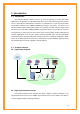
6. Interface Setup The physical connections determine whether the router ports are local area network (LAN) ports or wide area network (WAN) ports. There are two kinds of IP networks. The local, private kind is the LAN network; the global, public kind is the WAN network. The following illustration shows the relationship between the router and the two different networks. A LAN is a shared communication system to which many computers are attached.
6.1.1 ATM VC & QoS ATM settings are used to connect to your ISP. Your ISP provides VPI, VCI, settings to you. In this Device, you can totally setup 8 PVCs on different encapsulations if you apply 8 different virtual circuits from your ISP. You need to activate the VC to take effect. For PVCs management, you can use ATM QOS to setup each PVC traffic line’s priority. Virtual Circuit: Select the VC number you want to setup. VPI: Virtual Path Identifier. The valid range for the VPI is 0 to 255.
time, more cells (up to the MBS) can be sent at the PCR again. CBR is for connections that support constant rates of data transfer. The only parameter you need to worry about in CBR is PCR. UBR is for connections that have variable traffic. The only parameter you need to worry about in UBR is PCR. rtVBR is for connections that, while having variable traffic, require precise timing between traffic source and destination. PCR, SCR and MBS must all be set for rtVBR.
(2) Static IP Address Select this option to set static IP information. You will need to enter in the encapsulation type (1483 Bridged IP LLC, 1483 Bridged IP VC-Mux, 1483 Routed IP LLC (IPoA), 1483 Routed IP VC-Mux), IP address, subnet mask, and gateway address provided to you by your ISP. Each IP address entered in the fields must be in the appropriate IP form, which is 4 IP octets separated by a dot (x.x.x.x). The Router will not accept the IP address if it is not in this format.
LABEL DESCRIPTION Username Enter your username for your PPPoE/PPPoA connection. Password Enter your password for your PPPoE/PPPoA connection. Encapsulation Select your encapsulation type from the dropdown list. Bridge Interface Select whether the Interface will be Activated or Deactivated. Connection Select whether your connection is always on or if it connects on demand. If on demand, specify how many minutes the connection may be idle before it disconnects.
Connection Setting: For PPPoE/PPPoA connection, you can select Always on or Connect on-demand. Connect on demand is dependent on the traffic. If there is no traffic (or Idle) for a pre-specified period of time, the connection will tear down automatically. And once there is traffic send or receive, the connection will be automatically on. IP Address: For PPPoE/PPPoA connection, you need to specify the public IP address for this ADSL Router.
The following table describes the labels in this screen. LABEL Encapsulation DESCRIPTION Select your encapsulation type from the dropdown list. 6.2 LAN There are the IP settings of the LAN Interface for the device. These settings may be referred to as Private settings. You may change the LAN IP address if needed. The LAN IP address is provided to your internal network and cannot be seen on the Internet. 6.2.
Dynamic Route: Select the Dynamic Route from RIP1, RIP2-B, and RIP2-M. Please refer to InternetÆ Dynamic Route. The only difference is the interface. IGMP Snoop: You can disabled and enabled IGMP Snoop function. 6.2.2 Explaining RIP Setup Routing Information Protocol (RIP) allows a router to exchange routing information with other routers. The RIP Direction field controls how RIP packets are allowed to enter and leave the router.
LABEL Starting IP Address DESCRIPTION Enter the starting IP address you wish to use as the DHCP server's IP assignment. IP Pool Count Enter the maximum user pool size you wish to allow. Lease Time Enter the amount of time you wish to lease out a given IP address. DNS Relay Select the DNS relay option you wish to use from the dropdown list. Primary DNS Server Enter the primary DNS server IP address you wish to use. For user discovered DNS only.
6.2.5 DNS Relay The DNS Configuration allows the user to set the configuration of DNS. DNS Rely Selection: If user wants to disable this feature, he just needs to set both Primary & Secondary DNS to 0.0.0.0. Using DNS relay, users can setup DNS server IP to 192.168.1.1 on their computer. If not, device will perform as NO DNS relay. If you don’t want to use the DNS Relay option, set the DNS relay to “Use User Discovered DNS Server Only” and set both Primary and Secondary DNS Servers to “0.0.0.0”.