IEEE 802.
FCC Warning This equipment has been tested and found to comply with the limits for a Class B digital device, pursuant to part 15 of the FCC Rules. These limits are designed to provide reasonable protection against harmful interference in a residential installation. This equipment generates, uses, and can radiate radio frequency energy and, if not installed and used in accordance with the instructions, may cause harmful interference to radio communication.
Copyright 2011 All Rights Reserved. No part of this document can be copied or reproduced in any form without written consent from the company. Trademarks: All trade names and trademarks are the properties of their respective companies.
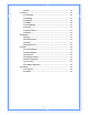
Table of Contents 1. Introduction................................................................................................................... 5 1.1 Features ............................................................................................................. 5 1.2 Package Contents ............................................................................................... 8 1.3 System Requirements.........................................................................................
3.6.6 RIP ....................................................................................................... 45 3.7 Advance ........................................................................................................... 46 3.7.1 ARP Table............................................................................................. 46 3.7.2 Bridging ............................................................................................... 47 3.7.3 Routing ............................
1. Introduction This full rate ADSL2+ router is an allͲinͲone Wireless ADSL2+ router for Home and SOHO applications. This gateway are with fullͲfeatured ADSL router that provides highͲspeed Internet access, 4Ͳport Ethernet switch direct connections to individual PCs or local area network with 10/100 BaseͲT Ethernet and a 300Mbps IEEE802.11n wireless connectivity.
Bridging / Routing support z Ethernet to ADSL selfͲlearning Transparent Bridging (IEEE 802.
z Firmware upgrade via FTP / TFTP z SNMP Support z HTTPS Support z BuiltͲin Diagnostic Tool z TRͲ069 support Network Address Translation (NAT) Network Address Translation (NAT) allows the translation of an Internet protocol address used within one network (for example a private IP address used in a local network) to a different IP address known within another network (for example a public IP address used on the Internet).
1.2 Package Contents Θʳ One ADSL Router Θʳ One CDͲROM (user’s manual) Θʳ One Ethernet Cable (RJͲ45) Θʳ One phone cable (RJͲ11) Θʳ One power adapter 1.3 System Requirements Θʳ Computers with an installed Ethernet adapter. Θʳ Valid Internet Access account and Ethernet based DSL or Cable modem. Θʳ 10/100BaseͲT Ethernet cable with RJͲ45 connector. Θʳ TCP/IP protocol must be installed on all PCs. Θʳ System with MS Internet Explorer ver. 5.0 or later, or Netscape Navigator ver. 4.7 or later.
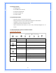
Back Panel Connectors Button/Port Description Reset Reset configurations to default. You would use the reset button only when a program error has caused your Wireless AP router to hang. Press the button and hold after 6 seconds. WPS Click WPS button 1 to 3 seconds while you are connecting a PC of wireless adapter with WPS function (you must enable WPS’ PBC function). LAN Ethernet RJͲ45 connector, connect to PC with a RJͲ45 Ethernet cable.
2. PC Configuration You can connect Wireless LAN ADSL2+ router with PC through either Ethernet cable. You can change the settings via WEB browser. 2.
Θʳ If you decide to use DHCP, select “Obtain an IP address automatically”, then click “OK” to confirm your settings. Once you restart your system, Wireless Router will obtain an IP address for this system. Θʳ If you decide to use fixed IP address for your system, select “Specify an IP address”, and make sure that IP Address and Subnet Mask are correct.
d) Select “DNS Configuration” tab and make sure select “Enable DNS”, enter the DNS address provides from your ISP in the “DNS Server Search Order” field, then click “Add”, Checking TCI/IP Setting for Windows NT4.
b) Click “Properties”, window below will appear. Θʳ Select the network card on your system from “Adapter” field. Θʳ If you decide to use IP address from Wireless Router, select “Obtain an IP address from a DHCP server”. Θʳ If you decide to use the IP address you are desired, select “Specify an IP address”. Make sure enter correct addresses in “IP Address” and “Subnet Mask” fields. Θʳ You must set Wireless Router’s IP address as “Default Gateway”.
Checking TCP/IP Settings for Windows 2000 a) Select “Start Æ Control Panel Æ Network and DialͲup Connection” and right click “Local Area Connection” then click “Properties”, 14
b) Select the “Internet Protocol (TCP/IP)” for the network card on your system, then click “Properties”, window below will appear. Θʳ If you decide to use IP address from Wireless Router, select “Obtain an IP address automatically”. Θʳ If you decide to use the IP address you are desired, select “Use the following IP address”. Make sure enter correct addresses in “IP Address” and “Subnet Mask” fields.
b) Select “Internet Protocol (TCP/IP)” then click “Properties”, window below will appear.
Θʳ If you decide to use IP address from Wireless Router, select “Obtain an IP address automatically”. Θʳ If you decide to use the IP address you are desired, select “Use the following IP address”. Make sure enter correct addresses in “IP Address” and “Subnet Mask” fields. Θʳ You must set Wireless Router’s IP address as “Default Gateway”.
Θʳ If you decide to use IP address from Wireless Router, select “Obtain an IP address automatically”. Θʳ If you decide to use the IP address you are desired, select “Use the following IP address”. Make sure enter correct addresses in “IP Address” and “Subnet Mask” fields. Θʳ You must set Wireless Router’s IP address as “Default Gateway”.
Configure IP address Automatically: b) Select “Obtain an IP address automatically” and “Obtain DNS server address automatically” Click “OK” to finish the configuration.
Configure IP Address Manually: c) Select “Use the following IP address” and “Use the following DNS server addresses”. IP address: Fill in IP address 192.168.1.x (x is a number between 2 to 254). Subnet mask: Default value is 255.255.255.0. Default gateway: Default value is 192.168.1.1. Preferred DNS server: Fill in preferred DNS server IP address. Alternate DNS server: Fill in alternate DNS server IP address.
If the communication link between your computer and router is not setup correctly, after you type ping 192.168.1.1 under DOS prompt following messages will appear: Pinging 192.168.1.1 with 32 bytes of data: Request timed out. Request timed out. Request timed out. This failure might be caused by cable issue or something wrong in configuration procedure. 3.
The main webpage will be displayed as below: 22
3.2 Status This page displays the ADSL router’s current status and settings. Click “Refresh” button to update the status. 3.3 LAN This page shows the current setting or LAN interface. You can set IP address and subnet mask for LAN interface in this page.
IP Address ͲͲ The IP Address which your LAN hosts use to identify the device’s LAN port. Subnet Mask ͲͲ LAN Subnet mask. Apply Change ͲͲ Click to save the setting to the configuration. New parameters will take effect after save into flash memory and reboot the system. 3.4 Wireless 3.4.1 Basic Settings This page is used to configure the parameters for wireless LAN clients who may connect to your Access Point.
Band: This is the range of frequencies the gateway will use to communicate with your wireless devices. As you’re looking for products in stores or on the Internet, you might notice that you can choose equipment that supports six different wireless networking technologies: 2.4 GHz(B), 2.4 GHz(G), 2.4 GHz(B+G), 2.4 GHz(N), 2.4 GHz(G+N), and 2.4 GHz(B+G+N). Mode: Default set to AP mode. SSID: Specify the network name.
mW Associated Clients: This table shows MAC address, transmission, reception packet counters and encrypted status for each associated wireless clients. 3.4.2 Advanced Settings These settings are only for more technically advanced users who have a sufficient knowledge about wireless LAN. These settings should not be changed unless you know what effect the change will have on your Access Point.
roaming clients, but it will be power consuming. Data Rate: Set the wireless data transfer rate to a certain value. Since most of wireless devices will negotiate with each other and pick a proper data transfer rate automatically, it’s not necessary to change this value unless you know what will happen after change the value. [Auto] is recommended to maximize performance.
WPAͲPersonal) or WPAͲ802.1x mode (RADIUS or WPAͲEnterprise). In the Personal mode, a preͲshared key or passphrase is used for authentication. In the Enterprise mode, which is more difficult to configure, the 802.1 x RADIUS servers and an Extensible Authentication Protocol (EAP) are used for authentication. PreͲShared Key Format: select Passphrase mode or Hex mode for the PreͲShared Key. PreͲShared Key: Enter the PreͲShared via using the Passphrase mode or Hex mode.
Access Point in a minute without any hassle. In PIN method (PINͲPersonal Identification Number), When your 11n router acts as a Registrar, your must enter “SelfͲPIN Number” on WPS configuration section, this Enrollee PIN code should be provided by the Enrollee. If your 11n router acts as an Enrollee, in WPS configuration section, the “Regenerate PIN” will automatically generate for you. The purpose of PIN code is to provide the security key to Registrar (AP/Server).
3.5 WAN There are three subͲmenus for WAN configuration: Channel Config, ATM Settings, and ADSL Settings. 3.5.1 Channel Configuration ADSL router comes with 8 ATM Permanent Virtual Channels (PVCs) at the most. There are mainly three operations for each of the PVC channels: add, delete, and modify. And there are several channel modes to be selected for each PVC channel. For each of the channel modes, the setting is quite different accordingly.
Add ͲͲ Click Add to complete the channel setup and add this PVC channel into configuration. Modify ͲͲ Select an existing PVC channel by clicking the radio button at the Select column of the Current ATM VC Table before we can modify the PVC channel. After selecting a PVC channel, we can modify the channel configuration at this page. Click Modify to complete the channel modification and apply to the configuration.
VPI ͲͲ Virtual Path Identifier. This is readͲonly field and is selected on the Select column in the Current ATM VC Table. VCI ͲͲ Virtual Channel Identifier. This is readͲonly field and is selected on the Select column in the Current ATM VC Table. The VCI, together with VPI, is used to identify the next destination of a cell as it passes through to the ATM switch.
MBS ͲͲ Maximum Burst Size, a traffic parameter that specifies the maximum number of cells that can be transmitted at the peak cell rate. Apply Changes ͲͲ Set new PVC OoS mode for the selected PVC. New parameters will take effect after save into flash memory and reboot the system. See section “Admin” for save details. Undo ͲͲ Discard your settings. 3.5.3 ADSL Settings The ADSL Settings page allows you to select any combination of DSL training modes.
ADSL Capability ͲͲ “Bitswap Enable”: Enable/Disable bitswap capability. “SRA Enable”: Enable/Disable SRA (seamless rate adaptation) capability. Tone Mask ͲͲ Choose tones to be masked. Masked tones will not carry any data. Apply Changes ͲͲ Click to save the setting to the configuration and the modem will be retrained. 3.6 Service There are three subͲmenus for Service configuration: DHCP Settings, DNS, Firewall, UPnP, and RIP. 3.6.
end of the Lease Time, the lease is either renewed or a new IP is issued by the DHCP server. The amount of time is in units of seconds. The default value is 86400 seconds (1 day). The value –1 stands for the infinite lease. Domain Name ͲͲ A userͲfriendly name that refers to the group of hosts (subnet) that will be assigned addresses from this pool. Apply Changes ͲͲ Set new DHCP server configuration. New parameters will take effect after save into flash memory and reboot the system.
3.6.2 DNS There are two submenus for the DNS Configuration: [DNS Server] and [Dynamic DNS]. [DNS Server] This page is used to select the way to obtain the IP addresses of the DNS servers. Attain DNS Automatically ͲͲ Select this item if you want to use the DNS servers obtained by the WAN interface via the autoͲconfiguration mechanism. Set DNS Manually ͲͲ Select this item to configure up to three DNS IP addresses. Apply Changes ͲͲ Set new DNS relay configuration.
DDNS provider ͲͲ There are two DDNS providers to be selected in order to register your device with: DynDNS and TZO. A charge may occur depends on the service you select. Hostname ͲͲ Domain name to be registered with the DDNS server User Name ͲͲ UserͲname assigned by the DDNS service provider. Password ͲͲ Password assigned by the DDNS service provider. Email ͲͲ Enter Email for TZO settings. Key ͲͲ Enter key for TZO settings.
Outgoing Default Action ͲͲ Specify the default action on the LAN to WAN forwarding path. Incoming Default Action ͲͲ Specify the default action on the WAN to LAN forwarding path. Apply Changes ͲͲ Click to save the setting of default actions to the configuration. Direction ͲͲ Traffic forwarding direction. Protocol ͲͲ There are 3 options available: TCP, UDP and ICMP. Rule Action ͲͲ Deny or allow traffic when matching this rule.
3.6.3.2 MAC Filtering The MAC filtering feature allows you to define rules to allow or deny frames through the device based on source MAC address, destination MAC address, and traffic direction. Outgoing Default Action ͲͲ Specify the default action on the LAN to WAN bridging/forwarding path. Incoming Default Action ͲͲ Specify the default action on the WAN to LAN bridging/forwarding path.
Port Forwarding entry will create a tunnel through your firewall so that the computers on the Internet can communicate to one of the computers on your LAN on a single port. Port Forwarding ͲͲ Check this item to enable or disable the portͲforwarding feature. Protocol ͲͲ There are 3 options available: TCP, UDP and Both. Local IP Address ͲͲ IP address of your local server that will be accessed by Internet.
URL Blocking ͲͲ Check this item to enable or disable the URL Blocking feature. Apply Changes ͲͲ Click to save the rule entry to the configuration. FQDN ͲͲ Enter URL link which you want to filter in this section; and then click Add to save the change. Delete Selected ͲͲ Delete the selected URL Blocking rules from the table. You can click the checkbox at the Select column to select the blocking rule. Delete All ͲͲ Delete all URL blocking rules from the table.
Domain Blocking ͲͲ Check this item to enable or disable the Domain Blocking feature. Apply Changes ͲͲ Click to save the rule entry to the configuration. Domain ͲͲ A userͲfriendly name that refers to the group of hosts (subnet) that will be blocked. Delete Selected ͲͲ Delete the selected Domain Blocking rules from the table. You can click the checkbox at the Select column to select the filtering rule. Delete All ͲͲ Delete all Domain Blocking rules from the table. 3.6.3.
DMZ Host ͲͲ Check this item to enable the DMZ feature. DMZ Host IP Address ͲͲ IP address of the local host. This feature sets a local host to be exposed to the Internet. Apply Changes ͲͲ Click to save the setting to the configuration. 3.6.4 IGMP Proxy IGMP proxy enables the system to issue IGMP host messages on behalf of hosts that the system discovered through standard IGMP interfaces.
3.6.5 UPnP The DSL device supports a control point for Universal Plug and Play (UPnP) version 1.0, and supports two key features: NAT Traversal and Device Identification. This feature requires one active WAN interface. In addition, the host should support this feature. In the presence of multiple WAN interfaces, select an interface on which the incoming traffic is present.
UPnP ͲͲ Enable/disable UPnP feature. WAN Interface ͲͲ Select WAN interface that will use UPnP from the dropͲdown lists. Apply Changes ͲͲ Click to save the setting to the system configuration. 3.6.6 RIP RIP is an Internet protocol you can set up to share routing table information with other routing devices on your LAN, at your ISP’s location, or on remote networks connected to your network via the ADSL line.
RIP ͲͲ Enable/disable RIP feature. Apply Changes ͲͲ Click to save the setting of this setting block to the system configuration Interface ͲͲ The name of the interface on which you want to enable RIP. Receive Mode ͲͲ Indicate the RIP version in which information must be passed to the DSL device in order for it to be accepted into its routing table. Send Mode ͲͲ Indicate the RIP version this interface will use when it sends its route information to other devices.
3.7.2 Bridging You can enable/disable Spanning Tree Protocol and set MAC address aging time in this page.
Ageing Time ͲͲ Set the Ethernet address ageing time, in seconds. After [Ageing Time] seconds of not having seen a frame coming from a certain address, the bridge will time out (delete) that address from Forwarding DataBase(fdb). 802.1d Spanning Tree ͲͲ Enable/disable the spanning tree protocol Apply Changes ͲͲ Save this bridge configuration. New configuration will take effect after saving into flash memory and rebooting the system.
Enable ͲͲ Check to enable the selected route or route to be added. Destination ͲͲ The network IP address of the subnet. The destination can be specified as the IP address of a subnet or a specific host in the subnet. It can also be specified as all zeros to indicate that this route should be used for all destinations for which no other route is defined (this is the route that creates the default gateway). Subnet Mask ͲͲ The network mask for the destination subnet.
servers. The DSL device can be managed locally or remotely by SNMP protocol. SNMP ͲͲ Enable/disable RIP feature. System Description ͲͲ System descriptions of the DSL device. System Contact ͲͲ Contact person and/or contact information for the DSL device. System Name ͲͲ An administratively assigned name for the DSL device. System Location ͲͲ The physical locations of the DSL device. System Object ID ͲͲ Vendor object identifier.
mapping of the ports. (3) Click “Apply Changes” button to save the changes. 3.7.6 IP QoS The DSL device provides a control mechanism that can provide different priority to different users or data flows. The QoS is enforced by the QoS rules in the QoS table. A QoS rule contains two configuration blocks: Traffic Classification and Action.
[Classification] IP QoS ͲͲ Enable/disable the IP QoS function. Source IP ͲͲ The IP address of the traffic source. Source Netmask ͲͲThe source IP netmask. This field is required if the source IP has been entered. Source Port ͲͲ The source port of the selected protocol. You cannot configure this field without entering the protocol first. Destination IP ͲͲ The IP address of the traffic destination. Destination Netmask ͲͲ The destination IP netmask.
classification rule. TOS (Type of Service) ͲͲ Select this field to mark the IP TOS bits in the packet that match this classification rule. 802.1p ͲͲ Select this field to mark the 3Ͳbit userͲpriority field in the 802.1p header of the packet that match this classification rule. Note that this 802.1p marking is workable on a given PVC channel only if the VLAN tag is enabled in this PVC channel. [QoS Quese] This page displays the list of QoS Queue Configuration. 3.7.
LAN ͲͲ Check/unͲcheck the services on the LAN column to allow/unͲallow the services access from LAN side; and “WAN”. WAN ͲͲ Check/unͲcheck the services on the WAN column to allow/unͲallow the services access from WAN side. WAN Port ͲͲ This field allows the user to specify the port of the corresponding service.
IP Pass through ͲͲ The available interfaces are listed. You have to select one for advanced configuration. Lease Time ͲͲ The Lease Time is the amount of time that a network user is allowed to maintain a network connection to the device using the current IP address. Allow LAN access – Check this option to enable the LAN access 3.8 Diagnostic The DSL device supports some useful diagnostic tools. 3.8.
Host Address ͲͲ The IP address you want to ping. 3.8.2 ATM Loopback In order to isolate the ATM interface problems, you can use ATM OAM loopback cells to verify connectivity between VP/VC endpoints, as well as segment endpoints within the VP/VC. ATM uses F4 and F5 cell flows as follows: о F4: used in VPs о F5: used in VCs An ATM connection consists of a group of points.
Select PVC ͲͲ Select the PVC channel you want to do the loopͲback diagnostic. Flow Type ͲͲ The ATM OAM flow type. The selection can be F5 Segment or F5 EndͲtoͲEnd. Loopback Location ID ͲͲ The loopback location ID is the field for the loopͲback cell. The default value is all Fs to indicate the endpoint of the segment or connection. 3.8.3 ADSL This page shows the ADSL diagnostic result. Click Start button to start the ADSL diagnostic.
3.8.4 Diagnostic Test The Diagnostic Test page shows the test results for the connectivity of the physical layer and protocol layer for both LAN and WAN sides. Select the Internet Connection ͲͲ The available WAN side interfaces are listed. You have to select one for the WAN side diagnostic. 3.9 Admin 3.9.1 Commit/Reboot Whenever you use the Web configuration to change system settings, the changes are initially placed in temporary storage.
Commit and Reboot ͲͲ Whenever you use the web console to change system settings, the changes are initially placed in temporary storage. To save your changes for future use, you can use the Commit/Reboot function. This function saves your changes from RAM to flash memory and reboot the system. IMPORTANT! Do not turn off your modem or press the Reset button while this procedure is in progress. 3.9.
3.9.3 Password The first time you log into the system, you use the default password. There are twoͲlevel logins: admin and user. The admin and user password configuration allows you to change the password for administrator and user.
User Name ͲͲ Selection of user levels are: admin and user. Old Password ͲͲ Enter the old password for this selected login. New Password ͲͲ Enter the new password here. Confirmed Password ͲͲ Enter the new password here again to confirm. 3.9.4 Upgrade Firmware To upgrade the firmware for the DSL device: о Click the Browse button to select the firmware file. о Confirm your selection. о Click the Upload button to start upgrading.
3.9.5 ACL Configuration The Access Control List (ACL) is a list of permissions attached to the DSL device. The list specifies who is allowed to access this device. If ACL is enabled, all hosts cannot access this device except for the hosts with IP address in the ACL table.
ACL Capability ͲͲ Enable/disable the ACL function Enable ͲͲ Check to enable this ACL entry Interface ͲͲ Select the interface domain: LAN or WAN IP Address ͲͲ Enter the IP address that allows access to this device. Subnet Mask ͲͲ Enter the Subnet Mask that allows access to this device. 3.9.6 Time Zone Simple Network Timing Protocol (SNTP) is a protocol used to synchronize the system time to the public SNTP servers.
Current Time ͲͲ The current time of the specified time zone. You can set the current time by yourself or configured by SNTP. Time Zone ͲͲ Select time zone in which the DSL device resides. Enable SNTP client update ͲͲ Enable the SNTP client to update the system clock. SNTP server ͲͲ The IP address or the host name of the SNTP server. You can select from the list or set it manually. 3.9.
[ACS] URL ͲͲ URL of the auto configuration server (ACS) provided by the ISP User Name ͲͲ Entry the User name for ACS which is provided by ISP. Password ͲͲ Entry the password for ACS which is provided by ISP. Periodic Inform Enable ͲͲ Enable/disables the RG to connect to the ACS periodically. If you enable this feature, you should enter a value in the Periodic Inform Interval field. Periodic Inform Interval ͲͲ This field is enabled only when the Periodic Inform Enabled field is checked.
Password ͲͲ Key in the password for ADSL router. Path ͲͲ The path for connection request. Default is “/tr069”. Port ͲͲ The port for connection request. Default is “7547”. [Certificate Management] CPE Certificate Password ͲͲ The password is for CPE certificate. CPE Certificate ͲͲ Browse CPE certificate which is provided by ISP server. The CPE may use online certificate enrollment with the CA associated with the ACS. The CPE must be provided with the information needed to contact this CA.
3.10.2 ADSL This page shows the ADSL line statistic information.