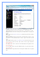
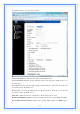
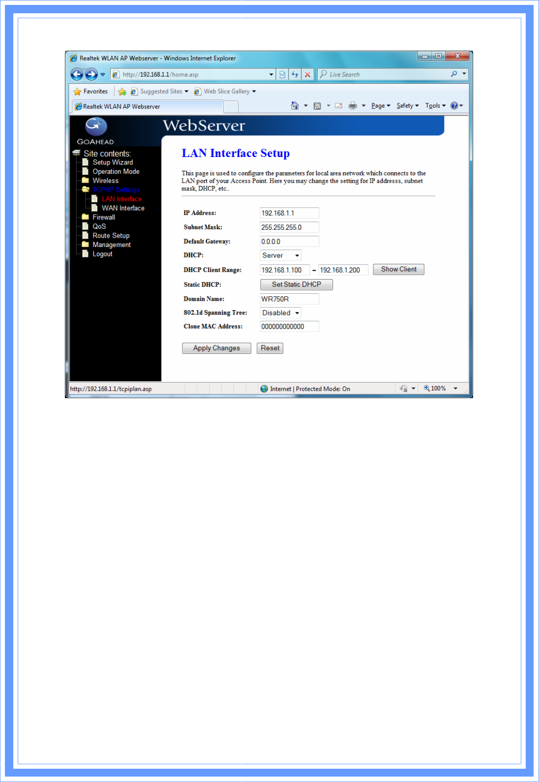
IP Address: Fill in the IP address of LAN interfaces of this WLAN Access Point. Subnet Mask: Fill in the subnet mask of LAN interfaces of this WLAN Access Point. Default Gateway: Fill in the default gateway for LAN interfaces out going data packets. DHCP: Click to select Disabled, Client or Server in different operation mode of wireless Access Point.
802.1d Spanning Tree: Select enable or disable the IEEE 802.1d Spanning Tree function from pull-down menu. Clone MAC Address: Fill in the MAC address that is the MAC address to be cloned. 3.5.1.1 Static DHCP Setup This page allows you reserve IP address and assign the same IP address to the network device with the specified MAC address any time it requests an IP address.
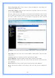
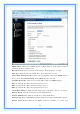
.5.2 WAN Interface This page is used to configure the parameters for wide area network that connects to the WAN port of your WLAN Broadband Router. Here you may change the access method to Static IP, DHCP, PPPoE or PPTP by click the item value of WAN Access Type. [Static IP] Static IP: Click to select Static IP support on WAN interface. There are IP address, subnet mask and default gateway settings need to be done.
DNS 1: Fill in the IP address of Domain Name Server 1. DNS 2: Fill in the IP address of Domain Name Server 2. DNS 3: Fill in the IP address of Domain Name Server 3. Clone MAC Address: Fill in the MAC address that is the MAC address to be cloned. Enable uPNP: Click the checkbox to enable uPNP function. Enable IGMP Proxy: Click the checkbox to enable IGMP Proxy. Enable Ping Access on WAN: Click the checkbox to enable WAN ICMP response.
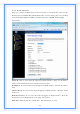
DHCP Client: Click to select DHCP support on WAN interface for IP address assigned automatically from a DHCP server. Host Name: Fill in the host name of Host Name. The default value is empty. MTU Size: Fill in the mtu size of MTU Size. The default value is 1400. Attain DNS Automatically: Click to select getting DNS address for DHCP support. Please select Set DNS Manually if the DHCP support is selected. Set DNS Manually: Click to select getting DNS address for DHCP support.
configuration from WAN side. Enable IPsec pass through on VPN connection: Click the checkbox to enable IPSec packet pass through. Enable PPTP pass through on VPN connection: Click the checkbox to enable PPTP packet pass through. Enable L2TP pass through on VPN connection: Click the checkbox to enable L2TP packet pass through. Apply Changes: Click the Apply Changes button to complete the new configuration setting. Reset: Click the Reset button to abort change and recover the previous configuration setting.
Set DNS Manually: Click to select getting DNS address for DHCP support. DNS 1: Fill in the IP address of Domain Name Server 1. DNS 2: Fill in the IP address of Domain Name Server 2. DNS 3: Fill in the IP address of Domain Name Server 3. Clone MAC Address: Fill in the MAC address that is the MAC address to be cloned. Enable uPNP: Click the checkbox to enable uPNP function. Enable IGMP Proxy: Click the checkbox to enable IGMP Proxy. Enable Ping Access on WAN: Click the checkbox to enable WAN ICMP response.
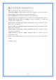
[PPTP] PPTP: Allow user to make a tunnel with remote site directly to secure the data transmission among the connection. User can use embedded PPTP client supported by this router to make a VPN connection. Get the WAN IP Automatically: Click to select PPTP Dynamic support on WAN interface for IP address assigned automatically from a PPTP server. IP Address: If you select the PPTP support on WAN interface, fill in the IP address for it.
for WAN interface out going data packets. Server IP Address : Enter the IP address of the PPTP Server. Server Domain Name: Assign Domain Name and dispatch to PPTP servers. It is optional field. User Name: If you select the PPTP support on WAN interface, fill in the user name and password to login the PPTP server. Password: you select the PPTP support on WAN interface, fill in the user name and password to login the PPTP server. MTU Size: Fill in the mtu size of MTU Size. The default value is 1400.
Please select Set DNS Manually if the PPTP support is selected. Set DNS Manually: Click to select getting DNS address for PPTP support. DNS 1: Fill in the IP address of Domain Name Server 1. DNS 2: Fill in the IP address of Domain Name Server 2. DNS 3: Fill in the IP address of Domain Name Server 3. Clone MAC Address: Fill in the MAC address that is the MAC address to be cloned. Enable uPNP: Click the checkbox to enable uPNP function. Enable IGMP Proxy: Click the checkbox to enable IGMP Proxy.
optional field. User Name: If you select the L2TP support on WAN interface, fill in the user name and password to login the PPTP server. Password: you select the L2TP support on WAN interface; fill in the user name and password to login the PPTP server. MTU Size: Fill in the MTU size of MTU Size. The default value is 1400. Request MPPE Encryption: Click the checkbox to enable request MPPE encryption. Attain DNS Automatically: Click to select getting DNS address for L2TP support.
DNS 3: Fill in the IP address of Domain Name Server 3. Clone MAC Address: Fill in the MAC address that is the MAC address to be cloned. Enable uPNP: Click the checkbox to enable uPNP function. Enable IGMP Proxy: Click the checkbox to enable IGMP Proxy. Enable Ping Access on WAN: Click the checkbox to enable WAN ICMP response. Enable Web Server Access on WAN: Click the checkbox to enable web configuration from WAN side.
Enable Port Filtering: Click to enable the port filtering security function. Port Range/Protocol/Comments: To restrict data transmission from the local network on certain ports, fill in the range of start-port and end-port, and the protocol, also put your comments on it. The Protocol can be TCP, UDP or Both. Comments let you know about whys to restrict data from the ports. 3.6.
Enable IP Filtering: Click to enable the IP filtering security function. Local IP Address/Protocol/Comments: To restrict data transmission from local network on certain IP addresses, fill in the IP address and the protocol; also put your comments on it. The Protocol can be TCP, UDP or Both. Comments let you know about whys to restrict data from the IP address. 3.6.
Enable MAC Filtering: Click to enable the MAC filtering security function. MAC Address/Comments: To restrict data transmission from local network on certain MAC addresses, fill in the MAC address and your comments on it. Comments let you know about whys to restrict data from the MAC address. 3.6.4 Port Forwarding Entries in this table allow you to automatically redirect common network services to a specific machine behind the NAT firewall.
Enable Port Forwarding: Click to enable the Port Forwarding security function. Local IP Address/Protocol/Port Range/Comment: To forward data packets coming from WAN to a specific IP address that hosted in local network behind the NAT firewall, fill in the IP address, protocol, port range and your comments. The Protocol can be TCP, UDP or Both. The Port Range is for data transmission. Comments let you know about whys to allow data packets forward to the IP address and port number. 3.6.
Enable URL Filtering: Click to enable the URL Filtering function. URL Address: Add one URL address. 3.6.6 DMZ A Demilitarized Zone is used to provide Internet services without sacrificing unauthorized access to its local private network. Typically, the DMZ host contains devices accessible to Internet traffic, such as Web (HTTP) servers, FTP servers, SMTP (e-mail) servers and DNS servers.
Enable DMZ: Click to enable the DMZ function. DMZ Host IP Address: To support DMZ in your firewall design, fill in the IP address of DMZ host that can be access from the WAN interface. 3.6.7 VLAN Enter in below table are used to configure VLAN settings. VLANs are created to provide the segmentation services traditionally provided by routers. VLANs address issue such as scalability, security, and network management. 3.
How to setup your QoS: 1. In QoS Setup Section, Enable QoS feature. 2. Choose Uplink & Downlink Speed: “Automatic” or “Manual” 3. Select Address Type: “IP” or “Address” 4. Configure QoS Rules – Mode(“Guaranteed Minimum bandwidth” & “Restricted Maximum bandwidth”), Uplink/Downlink Bandwidth, Comment. 5. Click “Apply Changes” to save QoS configurations. 3.8 Route Setup This page is used to setup dynamic routing protocol or edit static route entry.
[Dynamic Route] Dynamic routing is a technique developed to automatically adjust routing tables in the event of network failures. The most common dynamic routing protocols is RIP (Routing Information Protocol), which is very common on small networks. [Static Route] It menu allows you to define your own static routes for network traffic. Follow the instructions below to define a static router: 1. Enter the target IP address in the textbox near ‘IP Address’. 2.
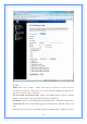
3.9 Management 3.9.1 Status This page shows the current status and some basic settings of the device, includes system, wireless, Ethernet LAN and WAN configuration information. [System] Uptime: It shows the duration since WLAN AP Router is powered on. Firmware version: It shows the firmware version of WLAN AP Router. [Wireless configuration] Mode: It shows wireless operation mode Band: It shows the current wireless operating frequency. SSID: It shows the SSID of this WLAN AP Router.
3.9.2 Statistics This page shows the packet counters for transmission and reception regarding to wireless, Ethernet LAN and Ethernet WAN networks.
[Wireless LAN] Sent Packets: It shows the statistic count of sent packets on the wireless LAN interface. Received Packets: It shows the statistic count of received packets on the wireless LAN interface. [Ethernet LAN] Sent Packets: It shows the statistic count of sent packets on the Ethernet LAN interface. Received Packets: It shows the statistic count of received packets on the Ethernet LAN interface.
Enable DDNS: Click the checkbox to enable DDNS service. Service Provider: Click the drop down menu to pickup the right provider. Domain Name: To configure the Domain Name. User Name/Email: Configure User Name, Email. Password/Key: Configure Password, Key. 3.9.4 Time Zone Setting Click the Reset button to abort change and recover the previous configuration setting. Current Time: It shows the current time. Time Zone Select: Click the time zone in your country.
3.9.5 Denial-of-Service This page is used to enable and setup protection to prevent attack by hacker’s program. It provides more security for users. Enable DoS Prevention: Click the checkbox to enable DoS prevention. Whole System Flood / Per-Source IP Flood…: Enable and setup prevention in details. Select ALL: Click the checkbox to enable all prevention items. Clear ALL: Click the checkbox to disable all prevention items. Apply Changes: Click the Apply Changes button to save above settings.
3.9.6 Log This page is used to configure the remote log server and shown the current log. Enable Log: Click the checkbox to enable log. System all: Show all log of wireless broadband router. Wireless: Only show wireless log DoS: Only show Denial-of-Service log Enable Remote Log: Click the checkbox to enable remote log service. Log Server IP Address: Input the remote log IP address. Apply Changes: Click the Apply Changes button to save above settings.
Refresh: Click the refresh the log shown on the screen. Clear: Clear log display screen. 3.9.7 Upgrade Firmware This page allows you upgrade the Access Point firmware to new version. Please note, do not power off the device during the upload because it may crash the system.
Select File: Click the Browse button to select the new version of web firmware image file. Upload: Click the Upload button to update the selected web firmware image to the WLAN Broadband Router. Reset: Click the Reset button to abort change and recover the previous configuration setting. 3.9.8 Save/Reload Setting This page allows you save current settings to a file or reload the settings from the file that was saved previously. Besides, you could reset the current configuration to factory default.
This page is used to set the account to access the web server of Access Point. Empty user name and password will disable the protection. User Name: Fill in the user name for web management login control. New Password: Fill in the password for web management login control. Confirmed Password: Because of the password input is invisible, fill in the password again for confirming purpose. Apply Changes: Clear the User Name and Password fields to empty, means to apply no web management login control.