1n Wireless Broadband Router User’s Manual APRIL 2011
FCC Warning This equipment has been tested and found to comply with the limits for a Class B digital device, pursuant to part 15 of the FCC Rules. These limits are designed to provide reasonable protection against harmful interference in a residential installation. This equipment generates, uses, and can radiate radio frequency energy and, if not installed and used in accordance with the instructions, may cause harmful interference to radio communication.
document is not up-to-date. Please check with your local distributors for the latest information. Copyright 2011 All Rights Reserved. No part of this document can be copied or reproduced in any form without written consent from the company. Trademarks: All trade names and trademarks are the properties of their respective companies.
Table of Contents 1. Introduction ........................................................................................................... 5 1.1 Features ...................................................................................................... 5 1.2 Specifications............................................................................................. 5 1.3 Package Contents..................................................................................... 7 1.4 System Requirements ....
3.6.2 IP Filtering.......................................................................................... 53 3.6.3 MAC Filtering.................................................................................... 54 3.6.4 Port Forwarding ............................................................................... 55 3.6.5 URL Filter............................................................................................ 56 3.6.6 DMZ ..................................................................
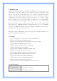
1. Introduction This Wireless Broadband Router complies with IEEE 802.11n, and provides faster and farther range than 802.11g while being backward compatible with 802.11g and 802.11b mode. This router uses advanced broadband router chipset and wireless LAN chipset solution to let you enjoy high-speed Wired and Wireless connection. Simply connect this device to a Cable or DSL modem and then you can share your high-speed Internet access with multiple PCs at your home with or without wires.
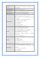
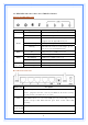
IEEE 802.11b / 802.11g / 802.11n (Wireless) Standard IEEE 802.3, IEEE 802.3u, IEEE 802.
Support Configuration setting Backup/Restore/Reset Default Interface LAN x 4, WAN x 1, USB2.0 LED Indicators POWER, STATUS, LAN x 4, WAN x 1, WLAN x 1 Antenna 1 Antennas Wireless Frequency 2.4000~2.4835GHz Output Power 15 dBm IEEE 802.11b : -88 dBm (Typical), IEEE 802.11g : -70dBm Receiver Sensitivity (Typical) IEEE 802.
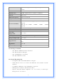
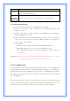
1.5 LEDs Indication & Connectors of Wireless Router Front Panel LEDs Indication LED Light Status PWR On Wireless Router is powered on. Off Wireless Router is powered off. On (Steady Green) Description Reset: When the router is resenting the configuration, the light will steady on Status Slow Blinking Flashing Status: System is up and ready. WPS: When the router is connecting a pc of wireless adapter with WPS function.
Cable modem or ADSL modem. DC-IN Power connector, connect to the power adapter (DC-5V, 2A) packaged with the AP router. USB Connect the 3G/3.5G USB device to USB Port. The 3G/3.5G USB port locates at right-side of the wireless router. 1.6 Installation Instruction 1) Power off 802.11n AP Router and DSL/Cable modem. 2) Connect computer to the LAN port on the Wireless Router with Ethernet cable. 3) Connect the DSL or Cable modem to the WAN port on the Wireless Router with Ethernet cable.
The 802.11n AP router assumes a DHCP IP address on the WAN side if connected to the network. In this case user can communicate with the same IP address 192.168.1.1 with PC connected to the LAN port. PC in the network can communicate with the DHCP IP address allocated to 802.11n router. 2.
‧ If you decide to use DHCP, select “Obtain an IP address automatically”, then click “OK” to confirm your settings. Once you restart your system, Wireless Router will obtain an IP address for this system. ‧ If you decide to use fixed IP address for your system, select “Specify an IP address”, and make sure that IP Address and Subnet Mask are correct.
d) Select “DNS Configuration” tab and make sure select “Enable DNS”, enter the DNS address provides from your ISP in the “DNS Server Search Order” field, then click “Add”, Checking TCI/IP Setting for Windows NT4.
b) Click “Properties”, window below will appear. ‧ Select the network card on your system from “Adapter” field. ‧ If you decide to use IP address from Wireless Router, select “Obtain an IP address from a DHCP server”.
‧ If you decide to use the IP address you are desired, select “Specify an IP address”. Make sure enter correct addresses in “IP Address” and “Subnet Mask” fields. ‧ You must set Wireless Router’s IP address as “Default Gateway”. c) To enter DNS address is provided from your ISP. Select “DNS” tab, click “Add” under “DNS Service Search Order” list, then enter DNS Server IP address in “TCP/IP DNS Server” window and click “Add”.
b) Select the “Internet Protocol (TCP/IP)” for the network card on your system, then click “Properties”, window below will appear.
‧ If you decide to use IP address from Wireless Router, select “Obtain an IP address automatically”. ‧ If you decide to use the IP address you are desired, select “Use the following IP address”. Make sure enter correct addresses in “IP Address” and “Subnet Mask” fields. ‧ You must set Wireless Router’s IP address as “Default Gateway”. ‧ If the DNS Server fields are empty, select “Use the following DNS server addresses” and enter the DNS address is provided by your ISP, then click “OK”.
‧ If you decide to use IP address from Wireless Router, select “Obtain an IP address automatically”. ‧ If you decide to use the IP address you are desired, select “Use the following IP address”. Make sure enter correct addresses in “IP Address” and “Subnet Mask” fields. ‧ You must set Wireless Router’s IP address as “Default Gateway”. ‧ If the DNS Server fields are empty, select “Use the following DNS server addresses” and enter the DNS address is provided by your ISP, then click “OK”.
b) Select “Internet Protocol (TCP/IP)” then click “Properties”, window below will appear.
‧ If you decide to use IP address from Wireless Router, select “Obtain an IP address automatically”. ‧ If you decide to use the IP address you are desired, select “Use the following IP address”. Make sure enter correct addresses in “IP Address” and “Subnet Mask” fields. ‧ You must set Wireless Router’s IP address as “Default Gateway”. ‧ If the DNS Server fields are empty, select “Use the following DNS server addresses” and enter the DNS address is provided by your ISP, then click “OK”.
Configure IP Address Manually: c) Select “Use the following IP address” and “Use the following DNS server addresses”.
IP address: Fill in IP address 192.168.1.x (x is a number between 2 to 254). Subnet mask: Default value is 255.255.255.0. Default gateway: Default value is 192.168.1.1. Preferred DNS server: Fill in preferred DNS server IP address. Alternate DNS server: Fill in alternate DNS server IP address. ‧ If you decide to use IP address from Wireless Router, select “Obtain an IP address automatically”. ‧ If you decide to use the IP address you are desired, select “Use the following IP address”.
Request timed out. Request timed out. This failure might be caused by cable issue or something wrong in configuration procedure. 3. Configure Wireless Router via Web Based Utility The Wireless Router implements a Web server allowing user configure this device via the web based Utility. This Utility provides comprehensive system management scheme, including system configuration, performance monitoring, system maintenance and administration. 3.
Step3: After log in, you can see the Main menu as below. 3.2 Setup Wizard This page guides you to configure wireless broadband router for first time.
3.2.1 Operation Mode This page followed by Setup Wizard page to define the operation mode.
3.2.2 Time Zone Setting This page is used to enable and configure NTP client. 3.2.3 LAN Interface Setup This page is used to configure local area network IP address and subnet mask.
3.2.4 WAN Interface Setup This page is used to configure WAN access type 3.2.
This page is used to configure basic wireless parameters like Band, Mode, Network Type SSID, Channel Number, Enable Mac Clone(Single Ethernet Client). 3.2.6 Wireless Security Setup This page is used to configure wireless security.
3.3 Operation Mode This page is used to configure which mode wireless broadband router acts. Gateway: Traditional gateway configuration. It always connects internet via ADSL/Cable Modem. LAN interface, WAN interface, Wireless interface, NAT and Firewall modules are applied to this mode. Bridge: Each interface (LAN, WAN and Wireless) regards as bridge. NAT, Firewall and all routers’ functions are not supported. Wireless ISP: Switch Wireless interface to WAN port and all Ethernet ports in bridge mode.
Disable Wireless LAN Interface: Click on to disable the wireless LAN data transmission. Band: This is the range of frequencies the gateway will use to communicate with your wireless devices. As you’re looking for products in stores or on the Internet, you might notice that you can choose equipment that supports six different wireless networking technologies: 2.4 GHz(B), 2.4 GHz(G), 2.4 GHz(B+G), 2.4 GHz(N), 2.4 GHz(G+N), and 2.4 GHz(B+G+N).
Identifier (SSID). When you set up your wireless adapter, you specify the SSID. If you want to connect to an existing network, you must use the make up your own name and use it on each computer. The name can be up to 32 characters long and contain letters and numbers. Channel Width: There have 2 options – 20MHZ and 40 MHZ [N band only]. Control Sideband: Specify if the extension channel should be in the Upper or Lower sideband [N band only]. Channel Number: Sets the channel on which the gateway operates.
Fragment Threshold: Fragmentation Threshold sets the frame size of incoming messages (ranging from 256 to 2346 bytes) used as fragmentation boundary. If the frame size is too big, the heavy interference affects transmission reliability. If the frame size is too small, it decreases transmission efficiency. Default setting is 2346. RTS Threshold: Lower the signal RTS (Request To Send) to promote the transmission efficiency in condition of noisy environment or too many clients. Default setting is 2347.
IAPP: Click to enable or disable the IAPP function. Protection: Protect 802.11n user priority. Aggregation: Click to enable or disable the Aggregation function. Short GI: Using a short (400ns) guard interval can increase throughput. However, it can also increase error rate in some installations, due to increased sensitivity to radio-frequency reflections WLAN Partition: Click to enable or disable the WLAN Partition function. STBC: Click to enable or disable the STBC function.
Shared Key or Auto selection. Key Length: Select the WEP shared secret key length from pull-down menu. The length can be chose between 64-bit and 128-bit (known as “WEP2”) keys. The WEP key is composed of initialization vector (24 bits) and secret key (40-bit or 104-bit). Key Format: Select the WEP shared secret key format from pull-down menu. The format can be chose between plant text (ASCII) and hexadecimal (HEX) code. Encryption Key: Secret key of WEP security encryption function.
Wireless Access Control Mode: Click the Disabled, Allow Listed or Deny Listed of drop down menu choose wireless access control mode. This is a security control function; only those clients registered in the access control list can link to this WLAN Broadband Router. MAC Address: Fill in the MAC address of client to register this WLAN Broadband Router access capability. Comment: Fill in the comment tag for the registered client.
Enable WDS: Click the check box to enable wireless distribution system. MAC Address: Fill in the MAC address of AP to register the wireless distribution system access capability. Data Rate: Select the transmission data rate from pull-down menu. Data rate: can be auto-select, 1M to 54Mbps or MCS. Comment: Fill in the comment tag for the registered AP. Apply Changes: Click the Apply Changes button to complete the new configuration setting.
3.4.6 Site Survey This page is used to view or configure other APs near yours. SSID: It shows the SSID of AP. BSSID: It shows BSSID of AP. Channel: It show the current channel of AP occupied. Type: It show which type AP acts. Encrypt: It shows the encryption status. Signal: It shows the power level of current AP. Refresh: Click the Refresh button to re-scan site survey on the screen. Connect: Click the Connect button to establish connection 3.4.
Disable WPS: Click on to disable the Wi-Fi Protected Setup function. WPS Status: Show WPS status is Configured or UnConfigured. Self-PIN Number: Fill in the PIN Number of AP to register the wireless distribution system access capability. Push Button Configuration: The Start PBC button provides tool to scan the wireless network. If any Access Point or IBSS is found, you could connect it automatically when client join PBC mode.
3.5 TCP/IP Settings 3.5.1 LAN Interface This page is used to configure the parameters for local area network that connects to the LAN ports of your WLAN Broadband Router. Here you may change the setting for IP address, subnet mask, DHCP, etc.
IP Address: Fill in the IP address of LAN interfaces of this WLAN Access Point. Subnet Mask: Fill in the subnet mask of LAN interfaces of this WLAN Access Point. Default Gateway: Fill in the default gateway for LAN interfaces out going data packets. DHCP: Click to select Disabled, Client or Server in different operation mode of wireless Access Point.
802.1d Spanning Tree: Select enable or disable the IEEE 802.1d Spanning Tree function from pull-down menu. Clone MAC Address: Fill in the MAC address that is the MAC address to be cloned. 3.5.1.1 Static DHCP Setup This page allows you reserve IP address and assign the same IP address to the network device with the specified MAC address any time it requests an IP address.
3.5.2 WAN Interface This page is used to configure the parameters for wide area network that connects to the WAN port of your WLAN Broadband Router. Here you may change the access method to Static IP, DHCP, PPPoE or PPTP by click the item value of WAN Access Type. [Static IP] Static IP: Click to select Static IP support on WAN interface. There are IP address, subnet mask and default gateway settings need to be done.
DNS 1: Fill in the IP address of Domain Name Server 1. DNS 2: Fill in the IP address of Domain Name Server 2. DNS 3: Fill in the IP address of Domain Name Server 3. Clone MAC Address: Fill in the MAC address that is the MAC address to be cloned. Enable uPNP: Click the checkbox to enable uPNP function. Enable IGMP Proxy: Click the checkbox to enable IGMP Proxy. Enable Ping Access on WAN: Click the checkbox to enable WAN ICMP response.
DHCP Client: Click to select DHCP support on WAN interface for IP address assigned automatically from a DHCP server. Host Name: Fill in the host name of Host Name. The default value is empty. MTU Size: Fill in the mtu size of MTU Size. The default value is 1400. Attain DNS Automatically: Click to select getting DNS address for DHCP support. Please select Set DNS Manually if the DHCP support is selected. Set DNS Manually: Click to select getting DNS address for DHCP support.
response. Enable Web Server Access on WAN: Click the checkbox to enable web configuration from WAN side. Enable IPsec pass through on VPN connection: Click the checkbox to enable IPSec packet pass through. Enable PPTP pass through on VPN connection: Click the checkbox to enable PPTP packet pass through. Enable L2TP pass through on VPN connection: Click the checkbox to enable L2TP packet pass through. Apply Changes: Click the Apply Changes button to complete the new configuration setting.
Idle Time: If you select the PPPoE and Connect on Demand connection type, fill in the idle time for auto-disconnect function. Value can be between 1 and 1000 minutes. MTU Size: Fill in the MTU size of MTU Size. The default value is 1400. Attain DNS Automatically: Click to select getting DNS address for DHCP support. Please select Set DNS Manually if the DHCP support is selected. Set DNS Manually: Click to select getting DNS address for DHCP support. DNS 1: Fill in the IP address of Domain Name Server 1.
[PPTP] PPTP: Allow user to make a tunnel with remote site directly to secure the data transmission among the connection. User can use embedded PPTP client supported by this router to make a VPN connection. Get the WAN IP Automatically: Click to select PPTP Dynamic support on WAN interface for IP address assigned automatically from a PPTP server. IP Address: If you select the PPTP support on WAN interface, fill in the IP address for it.
gateway for WAN interface out going data packets. Server IP Address : Enter the IP address of the PPTP Server. Server Domain Name: Assign Domain Name and dispatch to PPTP servers. It is optional field. User Name: If you select the PPTP support on WAN interface, fill in the user name and password to login the PPTP server. Password: you select the PPTP support on WAN interface, fill in the user name and password to login the PPTP server. MTU Size: Fill in the mtu size of MTU Size. The default value is 1400.
Attain DNS Automatically: Click to select getting DNS address for PPTP support. Please select Set DNS Manually if the PPTP support is selected. Set DNS Manually: Click to select getting DNS address for PPTP support. DNS 1: Fill in the IP address of Domain Name Server 1. DNS 2: Fill in the IP address of Domain Name Server 2. DNS 3: Fill in the IP address of Domain Name Server 3. Clone MAC Address: Fill in the MAC address that is the MAC address to be cloned.
mask for it. Gateway: If you select the Static L2TP support on WAN interface, fill in the gateway for WAN interface out going data packets. Server IP Address: Enter the IP address of the L2TP Server. Server Domain Name: Assign Domain Name and dispatch to L2TP servers. It is optional field. User Name: If you select the L2TP support on WAN interface, fill in the user name and password to login the PPTP server.
Request MPPE Encryption: Click the checkbox to enable request MPPE encryption. Attain DNS Automatically: Click to select getting DNS address for L2TP support. Please select Set DNS Manually if the L2TP support is selected. Set DNS Manually: Click to select getting DNS address for L2TP support. DNS 1: Fill in the IP address of Domain Name Server 1. DNS 2: Fill in the IP address of Domain Name Server 2. DNS 3: Fill in the IP address of Domain Name Server 3.
AP Router is powered on. Connect on Demand connection type means to setup the connection through USB3G protocol whenever you send the data packets out through the WAN interface; there are a watchdog implemented to close the USB3G connection while there are no data sent out longer than the idle time set. Manual connection type means to setup the connection through the USB3G protocol by clicking the Connect button manually, and clicking the Disconnect button manually.
configuration setting. 3.6 Firewall 3.6.1 Port Filtering Entries in this table are used to restrict certain types of data packets from your local network to Internet through the Gateway. Use of such filters can be helpful in securing or restricting your local network.
Enable Port Filtering: Click to enable the port filtering security function. Port Range/Protocol/Comments: To restrict data transmission from the local network on certain ports, fill in the range of start-port and end-port, and the protocol, also put your comments on it. The Protocol can be TCP, UDP or Both. Comments let you know about whys to restrict data from the ports. 3.6.
Enable IP Filtering: Click to enable the IP filtering security function. Local IP Address/Protocol/Comments: To restrict data transmission from local network on certain IP addresses, fill in the IP address and the protocol; also put your comments on it. The Protocol can be TCP, UDP or Both. Comments let you know about whys to restrict data from the IP address. 3.6.
Enable MAC Filtering: Click to enable the MAC filtering security function. MAC Address/Comments: To restrict data transmission from local network on certain MAC addresses, fill in the MAC address and your comments on it. Comments let you know about whys to restrict data from the MAC address. 3.6.4 Port Forwarding Entries in this table allow you to automatically redirect common network services to a specific machine behind the NAT firewall.
Enable Port Forwarding: Click to enable the Port Forwarding security function. Local IP Address/Protocol/Port Range/Comment: To forward data packets coming from WAN to a specific IP address that hosted in local network behind the NAT firewall, fill in the IP address, protocol, port range and your comments. The Protocol can be TCP, UDP or Both. The Port Range is for data transmission. Comments let you know about whys to allow data packets forward to the IP address and port number. 3.6.
Enable URL Filtering: Click to enable the URL Filtering function. URL Address: Add one URL address. 3.6.6 DMZ A Demilitarized Zone is used to provide Internet services without sacrificing unauthorized access to its local private network. Typically, the DMZ host contains devices accessible to Internet traffic, such as Web (HTTP) servers, FTP servers, SMTP (e-mail) servers and DNS servers.
Enable DMZ: Click to enable the DMZ function. DMZ Host IP Address: To support DMZ in your firewall design, fill in the IP address of DMZ host that can be access from the WAN interface. 3.6.7 VLAN Enter in below table are used to configure VLAN settings. VLANs are created to provide the segmentation services traditionally provided by routers. VLANs address issue such as scalability, security, and network management.
3.7 QoS Entries in this table improve your online gaming experience by ensuring that your game traffic is prioritized over other network traffic, such as FTP or Web.
How to setup your QoS: 1. In QoS Setup Section, Enable QoS feature. 2. Choose Uplink & Downlink Speed: “Automatic” or “Manual” 3. Select Address Type: “IP” or “Address” 4. Configure QoS Rules – Mode(“Guaranteed Minimum bandwidth” & “Restricted Maximum bandwidth”), Uplink/Downlink Comment. 5. Click “Apply Changes” to save QoS configurations.
3.8 Route Setup This page is used to setup dynamic routing protocol or edit static route entry. [Dynamic Route] Dynamic routing is a technique developed to automatically adjust routing tables in the event of network failures. The most common dynamic routing protocols is RIP (Routing Information Protocol), which is very common on small networks. [Static Route] It menu allows you to define your own static routes for network traffic. Follow the instructions below to define a static router: 1.
5. Select the correct port type in the dropdown box near ‘Interface’. 6. Click the ‘Apply Changes’ button to add the route. 3.9 Management 3.9.1 Status This page shows the current status and some basic settings of the device, includes system, wireless, Ethernet LAN and WAN configuration information. [System] Uptime: It shows the duration since WLAN AP Router is powered on. Firmware version: It shows the firmware version of WLAN AP Router.
WLAN AP Router and shared among its service area, so all device sat tempts to join the same wireless network can identify it. Channel Number: It shows the wireless channel connected currently. Encryption: It shows the status of encryption function. Associated Clients: It shows the number of connected clients (or stations, PCs). BSSID: It shows the BSSID address of the WLAN AP Router BSSID is a six-byte address. [LAN configuration] IP Address: It shows the IP address of LAN interfaces of WLAN AP Router.
3.9.2 Statistics This page shows the packet counters for transmission and reception regarding to wireless, Ethernet LAN and Ethernet WAN networks. [Wireless LAN] Sent Packets: It shows the statistic count of sent packets on the wireless LAN interface. Received Packets: It shows the statistic count of received packets on the wireless LAN interface. [Ethernet LAN] Sent Packets: It shows the statistic count of sent packets on the Ethernet LAN interface.
Received Packets: It shows the statistic count of received packets on the Ethernet WAN interface. Refresh: Click the refresh the statistic counters on the screen. 3.9.3 DDNS This page is used to configure Dynamic DNS service to have DNS with dynamic IP address. Enable DDNS: Click the checkbox to enable DDNS service. Service Provider: Click the drop down menu to pickup the right provider. Domain Name: To configure the Domain Name. User Name/Email: Configure User Name, Email.
Current Time: It shows the current time. Time Zone Select: Click the time zone in your country. Enable NTP client update: Click the checkbox to enable NTP client update. NTP Server: Click select default or input NTP server IP address. Apply Change: Click the Apply Changes button to save and enable NTP client service. Reset: Click the Reset button to abort change and recover the previous configuration setting. Refresh: Click the refresh the current time shown on the screen. 3.9.
3.9.6 Log This page is used to configure the remote log server and shown the current log. Enable Log: Click the checkbox to enable log. System all: Show all log of wireless broadband router. Wireless: Only show wireless log DoS: Only show Denial-of-Service log Enable Remote Log: Click the checkbox to enable remote log service. Log Server IP Address: Input the remote log IP address. Apply Changes: Click the Apply Changes button to save above settings. Refresh: Click the refresh the log shown on the screen.
Clear: Clear log display screen. 3.9.7 Upgrade Firmware This page allows you upgrade the Access Point firmware to new version. Please note, do not power off the device during the upload because it may crash the system.
Select File: Click the Browse button to select the new version of web firmware image file. Upload: Click the Upload button to update the selected web firmware image to the WLAN Broadband Router. Reset: Click the Reset button to abort change and recover the previous configuration setting. 3.9.8 Save/Reload Setting This page allows you save current settings to a file or reload the settings from the file that was saved previously. Besides, you could reset the current configuration to factory default.
Save Settings to File: Click the Save button to download the configuration parameters to your personal computer. Load Settings from File: Click the Browse button to select the configuration files then click the Upload button to update the selected configuration to the WLAN Broadband Router. Reset Settings to Default: Click the Reset button to reset the configuration parameter to factory defaults. 3.9.9 Password This page is used to set the account to access the web server of Access Point.
User Name: Fill in the user name for web management login control. New Password: Fill in the password for web management login control. Confirmed Password: Because of the password input is invisible, fill in the password again for confirming purpose. Apply Changes: Clear the User Name and Password fields to empty, means to apply no web management login control. Click the Apply Changes button to complete the new configuration setting.