
User guide

Installation Instructions
Ford Escape, (Includes Hybrid)
Mercury Mariner, (Includes Hybrid)
Mazda Tribute
Part Numbers:
51194
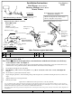
Hitch Shown In Proper Position
Wiring Access Location: SUV1, SUV2
Equipment Required: Pull wire ( Provided)
Do Not Exceed Lower of Towing Vehicle
Manufacturer’s Rating or
Drawbar must be used in the
DROP
position only.
Drawbar Kit:
36051
Ft Kit
51194F
3500 LB (1589 Kg) Max Gross Trailer Weight
300 LB (136 Kg) Max Tongue Weight
Wrenches: 7/8”
Drill Bits: 1” & 3/8”
(If tie down bracket present)
1
2
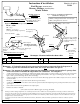
Drilled access hole
See Figure 1.
F
as
t
ener
Kit
:
51194F
Driver's side frame rail
End of frame
access hole
passenger side
Rearward of vehicle
43
Rearward hole
passenger
side
.
*Check driver’s
side frame.
5-1/8”
5/8”
3/8" Dia.
Drill first
Impact bar
1" Dia - Drill after
3/8" hole
A h l d ill l ti
Kink pull wire to
keep block
Figure 2.
Optional installation
with tie down bracket.
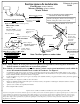
Note: If there is access holes to put the bolts & spacers into the frame rails from the end on both sides
1
Qty. (4) Carriage Bolt 1/2-13 X 1.75
3
Qty. (4) Conical Washer
2
Qty. (4) Spacer
4
Qty. (4) Hex Nut 1/2-13
Note: Fasteners typical both sides
A
ccess
h
o
l
e
d
r
ill
l
oca
ti
on
driver side frame rail with tie
down bracket
independent of bolt
Figure 1
.
Figure 3.
Note:
If
there
is
access
holes
to
put
the
bolts
&
spacers
into
the
frame
rails
from
the
end
on
both
sides
there is no
need to drill.
Note: Due to variation in tie down brackets, some interference with the end of frame access hole may
occur on driver’s side. See Figure 1.
1. Using the pull wire insert carriage bolt and spacer using the kink pull wire method (Figure 3) into the rearward holes of the
each frame rail. Leave pull wires attached. If interfere with tie down bracket exists see Figure 1.
2. Feed pull wire through the slots in the hitch.
3
R i hit h i t iti d t i b lt ll i d tt h i l h d t H d ti ht th
3
.
R
a
i
se
hit
c
h
i
n
t
o pos
iti
on an
d
on
t
o carr
i
age
b
o
lt
s remove pu
ll
w
i
re an
d
a
tt
ac
h
con
i
ca
l
was
h
ers an
d
nu
t
s.
H
an
d
ti
g
ht
en
th
e
fasteners.
Note: Be careful not to push fasteners back into frame.
4. Repeat using the pull wire to insert remaining carriage bolt and spacer into each frame rail using the same access holes as in
Step 1.
5. Tighten all fasteners to listed specification.
6. Paint any bare metal.
z 2010 Cequent Performance Products
Sheet 1 of 3 51194N 4-28-10 Rev. A
Note: check hitch frequently, making sure all fasteners and ball are properly tightened. If hitch is removed, plug all holes in trunk pan or other body panels to
prevent entry of water and exhaust fumes. A hitch or ball which has been damaged should be removed and replaced. Observe safety precautions when working
beneath a vehicle and wear eye protection. Do not cut access or attachment holes with a torch.
This product complies with safety specifications and requirements for connecting devices and towing systems of the state of New York, V.E.S.C. Regulation V-5
and SAE J684.
Form F206 Rev A 5605
Tighten all ½-13 GR5 fasteners with torque wrench to 75 Lb.-Ft. (102 N*M)