
Instructions / Assembly


Manual Addendum – Insert this into your Scaffold Assembly and Operating Instructions Manual
200803 Manual Addendum
The maximum distributed load capacity decreases with the number of sections that are used. The total combined weight of
workers, material, and equipment must not exceed the rated working load.
Maximum Load Capacity Base Section - 1,000 Lbs (Workers & Materials) 2 Sections - 850 Lbs (Workers & Materials)
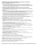
Install side braces, platform and guard rail at desired height. All four L-shaped lock pins must be inserted fully in holes on
frame. WARNING: Be certain the Pin is fully inserted into hole (Figure 1). Do not leave the Pin half-inserted (Figure 2).
Figure 1
Pin Is NOT Fully Engaged
Pin Is Fully Engaged (Locked)
Figure 2
Whenever units are stacked, outriggers are required. Do not use a utility scaffold over 1 frame high without outriggers. Failure
to use outriggers will make scaffold more likely to tip over, causing serious injury or death. You must install outriggers before
stacking the second scaffold unit.
Outriggers (GSORSET) and Guard Rail (GSGRS) are required when stacking. Maximum stack is 2 with GSORSET.
Guard rail must be installed so that gate swings inward over platform. Failure to install guard rail properly may result in serious
injury or death.
When accessing platform, climb over the top of end frame ladder – DO NOT SWING AROUND SIDE OF END FRAME.
Swinging around side of end frame will cause scaffold to tip over, resulting in serious injury or death.
For Stacking An Additional Unit, Follow These Instructions:
1. Erect the base unit first.
2. Install the casters into all 4 outriggers and secure each with lock pin. Set the caster brake on each.
3. Outrigger should be installed on each leg of the scaffold. Clamp the outrigger to the frame at 90° angle to the side brace.
Tighten clamp securely. Clamp must be flush against scaffold leg, and casters must be in contact with the surface.
4. Add second scaffold level by stacking the end frame over on top of the base unit end frame.
5. Install side braces, platform and guard rail at desired height. All four L-shaped lock pins must be inserted fully in holes
on frame. Be certain the Pin is fully inserted into hole (Figure 1). Do not leave the Pin half-inserted (Figure 2).
6. Add guard rail. NOTE: The guard rail does not fit on the frame! Install
the guard rail in the sockets on the side brace. (Figure 3).
Figure 2
Figure 1
Figure 3
Pin Is Fully Engaged (Locked)
Pin Is NOT Fully Engaged