2013 03 GENSD7D 7,000 Surge Watts / 5,500 Running Watts DIESEL GENERATOR INSTRUCTION MANUAL READ ALL INSTRUCTIONS AND WARNINGS BEFORE USING THIS PRODUCT. This manual provides important information on proper operation & maintenance. Every effort has been made to ensure the accuracy of this manual. These instructions are not meant to cover every possible condition and situation that may occur. We reserve the right to change this product at any time without prior notice.
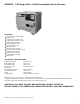
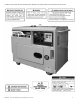
GENSD7D 7,000 Surge Watts / 5,500 Running Watts Diesel Generator FEATURES • Generator Type : 7,000 Surge Watt • Diesel Fuel Only • Self Excited, 2 Pole, Single Phase • Voltage Regulator: Automatic (AVR) • Starting System: Electric Start • Engine Displacement: 418cc • Engine Horsepower: 9 HP • Fuel Type: Diesel • Fuel Tank Capacity: 4 Gallons • Engine Run Time: 7 Hours @ Full Load • Engine Noise Level: <70 db • Automatic Low Oil Shutdown • Includes Wheels For Mobility • EPA Approved TECHNICAL SPECIFICATIONS
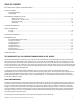
TABLE OF CONTENTS RECOGNIZE SAFETY SYMBOLS, WORDS AND LABELS .................................................................................................................................... 4 PACKAGE CONTENTS PACKAGE CONTENTS .............................................................................................................................................................................. 9 COMPONENTS ..............................................................................................
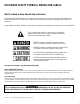
RECOGNIZE SAFETY SYMBOLS, WORDS AND LABELS What You Need to Know About Safety Instructions Warning and Important Safety Instructions appearing in this manual are not meant to cover all possible conditions and situations that may occur. Common sense, caution and care must be exercised when operating or cleaning tools and equipment. Always contact your dealer, distributor, service agent or manufacturer about problems or conditions you do not understand. This is the safety alert symbol.
IMPORTANT SAFETY INSTRUCTIONS STOP! Before using this generator and if you have any questions regarding the hazard and safety notices listed in this manual and/or on this generator, call 1-866-460-9436, Monday - Friday, 8 AM - 4 PM Central Time. Carbon Monoxide Gas: When in operation, the exhaust from this generator contains poisonous carbon monoxide gas. Carbon monoxide gas is both odorless and colorless AND may be present even if you do not see or smell gas.
High Temperatures: This generator produces heat when in operation. Temperatures near the exhaust can exceed 150 Degrees Fahrenheit (65 Degrees Celsius). • Do not touch hot surfaces. Observe all warning placards on this generator denoting hot surfaces. • Allow this generator to cool for several minutes after use before touching the engine, muffler or other areas that are hot during operation and before storing indoors. • Hot exhaust may ignite some materials.
GENSD7D 7,000 Surge Watts/5,500 Running Watts Diesel Generator 7
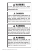
In addition to the previously described safety information, familiarize yourself with all safety and hazard placards on this generator.
PACKAGE CONTENTS The following items are supplied with this Model GENSD7D 7,000 Surge Watts / 5,500 Running Watts Diesel Generator. Verify all items are included. STOP! If there are missing items, call 1-866-460-9436, Monday - Friday, 8 AM - 4 PM Central Time for customer service. DO NOT RETURN THIS GENERATOR TO THE RETAILER.
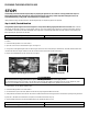
PREPARING THE GENERATOR FOR USE STOP! The following section describes the required steps for preparing this generator for use. Failure to correctly perform these steps can damage this generator and/or shorten its life. If still unsure about how to perform any of these steps after reading this section, call 1-866-460-9436 Monday - Friday, 8 AM - 4 PM Central Time for customer service.
Step 2 - Ground the Generator Failure to properly ground this generator can result in electrocution. Ground this generator by tightening the grounding nut against a grounding wire (Figure 3), found on the front of the battery. A No. 12 AWG (American Wire Gauge) stranded copper wire is generally an acceptable grounding wire. The other end of this grounding wire should be connected to a copper or brass-grounding rod that is driven into the earth. Grounding codes can vary by location.
USING THE GENERATOR Connect only electrical devices that are in good working order. Faulty devices or power cords present the risk of electrical shock. Immediately turn off and disconnect any device that commences to operate abnormally, sluggish or abruptly stops. Determine if the problem was the device or the rated load capacity of this generator has been exceeded. • USE THIS GENERATOR ONLY OUTDOORS IN NON-CONFINED AREAS.
NOTE: Plug appliances into the correct outlet. Connect standard 120 Volt, single phase, 60 Hz loads to the 120 Volt outlet. Connect 12 Volt, DC loads to the 12 Volt outlet. Even though this generator has an overall rated wattage of 7,000, do not attempt to draw more than 5,500 Watts from the 120 Volt and/or 240 Volt outlet. Draws higher than 5,500 Watts will damage this generator and void the warranty.
STOPPING THE GENERATOR Figure 10 To stop this generator: Figure 12 Figure 11 1. Turn off all connected electrical devices and then unplug them. 2. Switch the circuit breaker to the “OFF” position. (Figure 10) 3. Allow this generator to run for several more minutes with no electrical devices connected to help stabilize the temperature of this generator. 4. Set the engine Run lever to the “Stop” position. (Figure 11) 5. Turn the Starter switch to Off Position. (Figure 12).
Checking the Oil Level It is important to check the oil level in the engine crankcase before each use to ensure that there is a sufficient quantity. To check the oil level: 1. Verify that this generator is shut down and on a level surface. 2. Unscrew the oil filler/dipstick cap from the engine. 3. With a dry cloth, wipe the oil off of the dipstick that is located on the inside of the cap. 4. Insert the dipstick as if replacing the cap and then remove again. There should be oil on the dipstick.
Air Filter Maintenance ( Fuel Filter Maintenance) Routine maintenance of the air filter helps maintain proper airflow to the carburetor. Occasionally verify that the air filter is free of excessive dirt. The air filter will require more frequent cleaning when operating this generator in extremely dusty areas. To clean air filter, remove the access panel from side of generator, then remove wing nut to expose the element.
Replacing The Carbon Brushes 1. Remove Muffler Access Panel 4. Remove End Panel 2. Remove Dual Muffler System 5.Brush Assembly is Visible 3. Remove Both Mufflers 6. Locate Carbon Brushes 7. Replace Carbon Brushes TROUBLESHOOTING IMPORTANT: If trouble persists, call our customer help line at 1-866-460-9436, Monday - Friday, 8 AM - 4 PM Central Time. Symptom Engine will not start. (Figure 8) Engine runs but there is no electrical output. Cause Engine switch is set to "off.
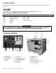
CONTROL PANEL ① ③ ④ Breaker Toggle Switch 120V/240V ② 6A 6B ⑥ ⑦ AC Voltage ③ Multi-function Display, relates to: ④ 1) Frequency (Hz) 6) Generator temp. (℃) 2) Current (Amps) 7) Blank 3) Battery voltage (V) 8) Auto protection indicator 4) Run time (Hours) 9) Diesel valve on indicator 5) Engine temp.
GENSD7D 7,000 SURGE WATTS / 5,500 RUNNING WATTS DIESEL GENERATOR PARTS DIAGRAM Push Rod GENSD7D 7,000 Surge Watts/5,500 Running Watts Diesel Generator 19
Valve Keeper First Piston Ring Second Piston Ring GENSD7D 7,000 Surge Watts/5,500 Running Watts Diesel Generator 20
Ball Bearing 6203 Ball Bearing 6308 GENSD7D 7,000 Surge Watts/5,500 Running Watts Diesel Generator 21
GENSD7D 7,000 Surge Watts/5,500 Running Watts Diesel Generator 22
Valve Cover GENSD7D 7,000 Surge Watts/5,500 Running Watts Diesel Generator 23
GENSD7D 7,000 Surge Watts/5,500 Running Watts Diesel Generator 24
1 1 120V AC Twist Lock Socket 120/240V AC Twist Lock Socket 1 1 1 1 GENSD7D 7,000 Surge Watts/5,500 Running Watts Diesel Generator 25
#8 is part of the rotor assembly. #7 is not part of the rotor assembly.
CONTROL PANEL WIRING DIAGRAM 38 40 39 GENSD7D 7,000 Surge Watts/5,500 Running Watts Diesel Generator 27
` Figure A – Remove side panel, then remove air filter. Locate the “Red” Decompression Lever (Photo above shows it in the UP position). Press the lever down – this will hold the exhaust valve open. Replace the air filter assembly. Start the engine. You will notice that the spring loaded lever will automatically return to the UP position. (Also referred to as the decompression shaft assembly on the parts diagram.) Figure B - Review the location of the AVR (Automatic Voltage Regulator.