
Manual


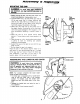

4.Remove the screw C and spacer in the lower
guard.
5,Slide slotted end of lower guard mounting
bracket under screw head and rotate lower
guard mounting bracket until hole in bracket
lines up with threaded hole ;n upper guard.
Threaded Hole
Mounting Bracket
Slotted
& Spacer
6.Replace' screw B, that was removed in step 3.
Tighten screw A and screw B.
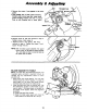
7. Replace screw C and spacer, that were
removed in step 4. Tighten the screw C and
spacer through the slot.
NOTE: With the blade guard attached, the guard
should raise as the blade is lowered towards
the work table and drop to cover the blade as
the power head is raised.
\
Screw B
iiiiiiiiiiiiiiii ii iii iiiiiii -
BLADE SQUARE TO TABLE
NOTE: The miter saw was assembled aligned and
inspected before shipment. Alignment should be
checked and any adjustments made to insure
accurate cuts,
!. Check miter lock handle setting. The miter lock
handle should be at the 0° position, To reset the
miter angle, turn the miter lock-handle counter
clockwise and press down the index spring.
2 Lower the blade and lock the handle latch, Use
the combination square to check blade square-
ness to table, If the blade does not contact the
full length of the square, follow the alignment
procedure.
a, Loosen the bevel lock handle.
b. Grasp the metal upper guard and move the
cutting head to the left as far as it will go,
10