
Manual
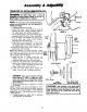
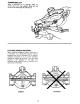

FILLER BLOCKS FOR CUTTING CROWN MOLDINGS
The majority of crown moldings have contact
surfaces of 52o and 38o to the rear surface of the
molding. When•joining the face of :_i!il_r i_
these angles must be mai_ined,:_Thei_ilowing
illustrations show two _m_:that can be used
when cuffing: cr0wn moldings depending on how
the flflerblock is attached to the fence.
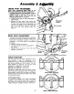
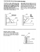
When the filler blocks are attached with the face of
the filler blocks pointing upwards, the molding
must be placed on the table upside down.
When the flilar blocks are attached to the fence
wtth_the face of the filler blocks pointing down-
wards, the molding must be placed on the table
right side up, This is the same position as it would
be when nailed between the ceiling and wail.
Make 2 filler blocks 10 inches long. Fasten blocks
securely to fence, For block lace pointing down-
ward, you may need to drill new fastener holes in
the fence.
Filler 8lock Face
Pointing Upward
Molding
Table
/
i
L
Fence Filler
S Block
Face
Pointing
_jDownward
.,..38__ M°ld|ng
1
i ii i i i i iiiiiiiiiiiiiiiiiiiiiiiiii iiiiii
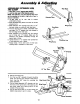
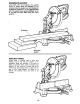
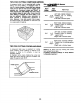
VERTICAL BEVEL CUTTING
To make a miter cut in a 2x4 workpiece (actual 1
5/8"x3 1/2") in the verticat position (on edge) a
spacer, such as the auxiliary fence described on
the previous page is required. Fence is located in
the front fence position.
Space Block
Fence
3-_-"(89 mm)
!
l i
j Workpiece
t
/ -- --_ 1"_L4'(41ram)
I
f
19