USER’S MANUAL EB-471LF ULV Celeron® M 3.
Copyright Notice EB-471LF Celeron® M 3.5” Embedded Card With VGA /Sound/LAN OPERATION MANUAL COPYRIGHT NOTICE This operation manual is meant to assist both Embedded Computer manufacturers and end users in installing and setting up the system. The information contained in this document is subject to change without any notice. This manual is copyrighted in April, 2006. You may not reproduce or transmit in any form or by any means, electronic, or mechanical, including photocopying and recording.
Copyright Notice FCC NOTICE This equipment has been tested and found to comply with the limits for a Class A digital device, pursuant to part 15 of the FCC Rules. These limits are designed to provide reasonable protection against harmful interference when the equipment is operated in a commercial environment. This equipment generates, uses, and can radiate radio frequency energy and, if not installed and used in accordance with the instruction manual, may cause harmful interference to radio communications.
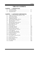
Contents TABLE OF CONTENTS CHAPTER 1-1 1-2 1-3 CHAPTER 2-1 2-2 2-3 2-4 2-5 2-6 2-7 2-8 2-9 2-10 2-11 2-12 2-13 2-14 2-15 2-16 2-17 2-18 2-19 2-20 2-21 2-22 2-23 2-24 2-25 2-26 1 INTRODUCTION About This Manual ........................................................ System Specification ...................................................... Safety Precautions ......................................................... 2 1-2 1-3 1-5 HARDWARE CONFIGURATION Jumper & Connector Quick Reference Table ......
Contents CHAPTER 3-1 3-2 3-3 3-4 3-5 3-6 3-7 3-8 CHAPTER 4-1 4-2 4-3 4-4 4-5 4-6 4-7 4-8 4-9 4-10 4-11 4-12 4-13 4-14 4-15 3 SOFTWARE UTILITIES Introduction …………..........................................…....... VGA Driver Utility ……………………………….…… Flash BIOS Update ..............................................…....... LAN Driver Utility …...........................................…...... Sound Driver Utility …………………………………… Intel Chipset Software Installation Utility …..……..….. USB2.
CHAPTER INTRODUCTION 1 This chapter gives you the information for EB-471LF. It also outlines the System specification. Section includes: z About This Manual z System Specifications z Safety precautions Experienced users can skip to chapter 2 on page 2-1 for Quick Start.
Chapter 1 Introduction 1-1. ABOUT THIS MANUAL Thank you for purchasing our EB-471LF Celeron® M3.5” Embedded Card enhanced with VGA /Sound/ LAN, which is fully PC / AT compatible. EB471LF provides faster processing speed, greater expandability and can handle more task than before. This manual is designed to assist you how to install and set up the system. It contains four chapters.
Chapter 1 Introduction 1-2. SYSTEM SPECIFICATION z CPU : Intel® Celeron® M processor Ultra Low Voltage without L2 cache onboard Available at 600MHz System bus frequency at 400MHz Auto detect voltage regulator z SYSTEM CHIPSET : Intel® 852GM chipset z MEMORY : Supports up to 1 GB DDR SDRAM. One 200-pin DDR SO-DIMM sockets on board z CACHE : Built-in CPU z REAL-TIME CLOCK / CALENDAR : 256-byte battery backed CMOS RAM.
Chapter 1 Introduction z DISPLAY : Built in Intel 852GM, support CRT, LCD. z IDE INTERFACE : One IDE ports support up to two IDE devices. Supports UDMA 33/66/100. z LAN INTERFACE : Intel® 82562ET 10/100 Base-T z SOUND: AC '97 Codec. Reatel ALC202A. Fully Compliant AC '97 Analog I/O Component z SERIAL PORT : Two high speed 16550 Compatible UARTs with Send / Receive 16 Byte FIFOs. COM1 for RS232; COM2 for RS232/422/485. z HARDWARE MONITORING FUNCTION : Monitor Voltage, CPU Temperature and Cooling Fan.
Chapter 1 Introduction z OPERATING TEMPERATURE : 0 to 60°C (32°F to 140°F) z INPUT POWER REQUIREMENT : AT power: +5V, +12V Only +5V: +5V only provide power for SBC, It does not have enough power to support expansion card. z BOARD DIMENSION : 102mm x 145mm (4.02” x 5.71”) z BOARD NET WEIGHT : 290 grams (0.64 lb) 1-3. SAFETY PRECAUTIONS Follow the messages below to avoid your systems from damage: 1. Avoid your system from static electricity on all occasions. 2. Prevent electric shock.
HARDWARE CONFIGURATION CHAPTER 2 ** QUICK START ** Helpful information describes the jumper & connector settings, and component locations.
Chapter 2 Hardware Configuration 2-1. JUMPER & CONNECTOR QUICK REFERENCE TABLE COM Port Connector ....................…..................……… RS232/422/485 (COM2) Selection .....................……… Keyboard/Mouse Connector ..........…………......…… Reset Connector .........................…....................………. Hard Disk Drive LED Connector .......................………. External Speaker Connector ....…........................……… Power LED Connector …………….…...............……… IrDA Connector ………………………………………..
Chapter 2 Hardware Configuration 2-2.
Chapter 2 Hardware Configuration 2-3. HOW TO SET THE JUMPERS You can configure your board by setting jumpers. Jumper is consists of two or three metal pins with a plastic base mounted on the card, and by using a small plastic "cap", Also known as the jumper cap (with a metal contact inside), you are able to connect the pins. So you can set-up your hardware configuration by "open" or "close" pins. The jumper can be combined into sets that called jumper blocks.
Chapter 2 Hardware Configuration JUMPER DIAGRAMS Jumper Cap looks like this 2 pin Jumper looks like this 3 pin Jumper looks like this Jumper Block looks like this JUMPER SETTINGS 2 pin Jumper close(enabled) Looks like this 1 1 3 pin Jumper 2-3 pin close(enabled) Looks like this 1 1 Jumper Block 1-2 pin close(enabled) Looks like this 1 2 EB-471LF USER′S MANUAL 1 2 Page: 2-5
Chapter 2 Hardware Configuration 2-4. COM PORT CONNECTOR COM1 : COM1 Connector COM1 is fixed as RS-232. The pin assignment is as follows : PIN 1 2 3 4 5 6 7 8 9 10 ASSIGNMENT DCD1 RX1 TX1 DTR1 GND DSR1 RTS1 CTS1 RI1 NC COM2 : COM2 Connector The COM2 is selectable as RS-232/422/485.
Chapter 2 Hardware Configuration 2-5. RS232/422/485 (COM2) SELECTION JP1 : RS-232/422/485 (COM2) Selection This connector is used to set the COM2 function. The jumper settings are as follows : COM 2 Function Jumper Settings (pin closed) RS-232 Open RS-422 1-2, 3-4, 9-10 RS-485 1-2, 5-6, 7-8 Jumper Illustrations *** Manufactory default --- RS-232.
Chapter 2 Hardware Configuration 2-6. KEYBOARD/MOUSE CONNECTOR DIN1 : Keyboard/Mouse Connector The pin assignments are as follows : PIN 1 2 3 5 6 8 ASSIGNMENT KB_DATA MS_DATA GND K/B_VCC KB_CLK MS_CLK 2-7. RESET CONNECTOR JPANEL1 (7,8) : Reset Connector. The pin assignment is as follows : PIN 7 8 ASSIGNMENT GND RST_SW 2-8.
Chapter 2 Hardware Configuration 2-9. EXTERNAL SPEAKER CONNECTOR JPANEL1 (5, 6) : External Speaker Connector The pin assignment is as follows : PIN 5 6 ASSIGNMENT SPK1 SPK_VCC 2-10. POWER LED CONNECTOR JPANEL1 (1, 3) : Power LED Connector The pin assignment is as follows: PIN 1 3 ASSIGNMENT VCC_R GND 2-11.
Chapter 2 Hardware Configuration 2-12. SYSTEM FAN CONNECTOR JSFAN1 : System Fan connector The pin assignment is as follows: PIN 1 2 3 ASSIGNMENT GND +12V FAN0 2-13.
Chapter 2 Hardware Configuration 2-14.
Chapter 2 Hardware Configuration 2-15. UNIVERSAL SERIAL BUS CONNECTOR USB1: Universal Serial Bus Connector The pin assignments are as follows: PIN 1 2 3 4 5 6 7 8 9 10 ASSIGNMENT VCCUSB0 USBP0N USBP0P GND GND VCCUSB0 USBP1N USBP1P GND GND 2-16.
Chapter 2 Hardware Configuration 2-17. CLEAR CMOS DATA SELECTION JP3 : Clear CMOS Data Selection The selections are as follows : FUNCTION JUMPER SETTING (pin closed) Normal Open Clear CMOS Close JUMPER ILLUSTRATION *** Manufacturing Default is set as Normal. Note: To clear CMOS data, user must power-off the computer and set the jumper to “Clear CMOS” as illustrated above. After five to six seconds, set the jumper back to “Normal” and power-on the computer.
Chapter 2 Hardware Configuration 2-18.
Chapter 2 Hardware Configuration 2-19. AT POWER CONNECTOR PW1 : AT Power Connector The pin assignments are as follows: PIN 1 2 3 4 ASSIGNMENT VCC12EX GND GND VCC 2-20.
Chapter 2 Hardware Configuration 2-21. RESET/NMI WATCHDOG SELECTION JP4 : Reset/NMI Watchdog Selection The selections are as follows: FUNCTION JUMPER SETTING (pin closed) RESET 1-2 NMI 3-4 JUMPER ILLUSTRATION ** Manufacturing default: Reset. User may select to use the Reset or NMI watchdog. NMI, also known as Non-Maskable Interrupt, is used for serious conditions that demand the processor’s immediate attention, it cannot be ignored by the system unless it is shut off specifically.
Chapter 2 Hardware Configuration 2-22. LVDS CONNECTOR LVDS1 : LVDS Connector.
Chapter 2 Hardware Configuration 2-23. PANEL VOLTAGE SELECTION JP5 : Panel Voltage Selection.
Chapter 2 Hardware Configuration 2-24. SOUND CONNECTOR J1 : Sound Connector. The pin assignments are as follows: PIN ASSIGNMENT 1 MIC-IN 2 NC 3 GND 4 GND 5 LINE-L 6 LINE-R 7 GND 8 GND 9 SPK-L 10 SPK-R 2-25. TV-OUT CONNECTOR JTV1 : TV-Out Connector.
Chapter 2 Hardware Configuration 2-26.
SOFTWARE UTILITIES CHAPTER 3 This chapter comprises the detailed information of VGA driver, LAN driver, and Flash BIOS update. It also describes how to install the watchdog timer configuration. Section includes: z VGA Driver Utility z Flash BIOS Update z LAN Driver Utility z Sound Driver Utility z Intel® Chipset Software Installation Utility z USB2.
Chapter 3 Software Configuration 3-1. INTRODUCTION Enclosed with our EB-471LF package is our driver utility, which may comes in a form of a CD ROM disc or floppy diskettes.
Chapter 3 Software Configuration 1. Win 9X program 2. Win NT4.0 program 3. Win 2000 program 4. Win XP program 3-2-1. Installation of VGA Driver: To install the VGA Driver, simply follow the following steps: 1. 2. 3. 4. 5. Place insert the Utility Disk into Floppy Disk Drive A/B or CD ROM drive. Under Windows 9X/NT4.0/2000/XP system, go to the directory where VGA driver is located. Click Setup.exe file for VGA driver installation. Follow the instructions on the screen to complete the installation.
Chapter 3 Software Configuration 3-3. FLASH BIOS UPDATE 3-3-1. System BIOS Update: Users of EB-471LF can use the program “Awdflash.exe” contained in the Utility Disk for system BIOS and VGA BIOS update. 3-3-2. To update VGA BIOS for LCD Flat Panel Display: As EB-471LF user, you have to update the VGA BIOS for your specific LCD flat panel you are going to use. For doing this, you need two files. One is the “Awdflash.
Chapter 3 Software Configuration FLASH MEMORY WRITER v7.XX (C) Award Software 2001 All Rights Reserved Flash Type – SST 49LF004A /3.3V File Name to Program: H20bxxxx.bin Checksum: XXXXX Error Message : Are You Sure To Program (Y/N) Select "Y", and the BIOS will be renewed. When you are refreshing the BIOS, do not turn off or reset the system, or you will damage the BIOS. After you have completed all the programming, the screen displays the table below: FLASH MEMORY WRITER v7.
Chapter 3 Software Configuration 3-4. LAN DRIVER UTILITY 3-4-1. Introduction EB-471LF is enhanced with LAN function that can support various network adapters. Installation programs for LAN drivers are listed as follows: 1. Win 98/2000/XP program 2. Linux program For more details on Installation procedure, please refer to Readme.txt file found on LAN DRIVER UTILITY.
Chapter 3 Software Configuration 3-5. SOUND DRIVER UTILITY 3-5-1. Introduction The Realtek ALC202A sound function enhanced in this system is fully compatible with Windows 98, Windows 98SE, Windows NT 4.0, Windows 2000, Windows ME and Windows XP. Below, you will find the content of the Sound driver : 1. Win 98SE program 2. Win NT 4.0 program 3. Win 2000 program 4. Win XP program 5. Linux program 3-5-2. Installation Procedure for Windows 9x/NT/2000/XP 1. 2. 3. 4. 5.
Chapter 3 Software Configuration 3-6. INTEL® CHIPSET SOFTWARE INSTALLATION UTILITY 3-6-1. Introduction The Intel® Chipset Software Installation Utility installs to the target system the Windows* INF files that outline to the operating system how the chipset components will be configured.
Chapter 3 Software Configuration 3-7. USB2.0 SOFTWARE INSTALLATION UTILITY 3-7-1. Installation of Utility for Windows 98SE/ 2000/XP Intel USB 2.0 Enhanced Host Controller driver can only be used on Windows 98SE, Windows 2000 and Windows XP on Intel Desktop boards. It should be installed right after the OS installation, kindly follow the following steps: 1. 2. 3. 4. 5. 6. 7. 8. 9. Place insert the Utility Disk into Floppy Disk Drive A/B or CD ROM drive.
Chapter 3 Software Configuration 3-8. WATCHDOG TIMER CONFIGURATION The I/O port address of the watchdog timer is 2E(hex) and 2F(hex). 2E (hex) is the address port. 2F(hex) is the data port. User must first assign the address of register by writing address value into address port 2E(hex), then write/read data to/from the assigned register through data port 2F (hex).
Chapter 3 Software Configuration Mov al, 07h ; Select Logical Device 8 of watchdog timer Out dx,al Inc dx Mov al, 08h Out dx,al ;----------------------------------------------------------Dec dx ; Set second as counting unit Mov al, 0f5h Out dx,al Inc dx In al,dx And al,not 08h Out dx,al ;----------------------------------------------------------Dec dx ; Set timeout interval as 30seconds and start counting Mov al, 0f6h Out dx,al Inc dx Mov al, 30 Out dx,al ;------------------------------------------------
CHAPTER AWARD BIOS SETUP 4 This chapter shows how to set up the Award BIOS.
Chapter 4 Award BIOS Setup 4-1. INTRODUCTION This chapter will show you the function of the BIOS in managing the features of your system. The EB-471LF Celeron® M Embedded CPU Card is equipped with the BIOS for system chipset from Award Software Inc. This page briefly explains the function of the BIOS in managing the special features of your system. The following pages describe how to use the BIOS for system chipset Setup menu.
Chapter 4 Award BIOS Setup 4-2. ENTERING SETUP When the system is powered on, the BIOS will enter the Power-On Self Test (POST) routines and the following message will appear on the lower screen: PRESS TO ENTER SETUP, ESC TO SKIP MEMORY TEST As long as this message is present on the screen you may press the key (the one that shares the decimal point at the bottom of the number keypad) to access the Setup program.
Chapter 4 Award BIOS Setup 4-3.
Chapter 4 Award BIOS Setup IDE Primary Master / Slave: IDE Secondary Master / Slave: The BIOS can automatically detect the specifications and optimal operating mode of almost all IDE hard drives. When you select type AUTO for a hard drive, the BIOS detect its specifications during POST, every time system boots. If you do not want to select drive type AUTO, other methods of selecting drive type are available: 1.
Chapter 4 Award BIOS Setup LBA (Logical Block Addressing): During drive accesses, the IDE controller transforms the data address described by sector, head and cylinder number into a physical block address, significantly improving data transfer rates. For drives greater than 1024 cylinders. DRIVE A AND DRIVE B: Select the type of floppy disk drive installed in your system. The available options are 360KB 5.25in, 1.2KB 5.25in, 720KB 3.5in, 1.44MB 3.5in, 2.88MB 3.5in and None.
Chapter 4 Award BIOS Setup HARD DISK ATTRIBUTES: Type 1 2 3 4 5 6 7 8 9 10 11 12 13 14 15 16 17 18 19 20 21 22 23 24 25 26 27 28 29 30 31 32 33 34 35 36 37 38 39 40 41 42 43 44 45 47 Cylinders 306 615 615 940 940 615 642 733 900 820 855 855 306 733 000 612 977 977 1024 733 733 733 306 977 1024 1224 1224 1224 1024 1024 918 925 1024 1024 1024 1024 1024 1024 918 820 1024 1024 809 809 776 Heads 4 4 6 8 6 4 8 5 15 3 5 7 8 7 0 4 5 7 7 5 7 5 4 5 9 7 11 15 8 11 11 9 10 12 13 14 2 16 15 6 5 5 6 6 8 V-P comp 12
Chapter 4 Award BIOS Setup 4-4. THE ADVANCED BIOS FEATURES Choose the〝ADVANCED BIOS FEATURES〞in the main menu, the screen shown as below.
Chapter 4 Award BIOS Setup FIRST/SECOND/ BOOT DEVICE: The BIOS attempt to load the operating system from the devices in the sequence selected in these items. BOOT UP NUMLOCK STATUS: Select power on state for NumLock. TYPEMATIC RATE SETTING: Enable this item if you wish to be able to configure the characteristics of your keyboard. Typematic refers to the way in which characters are entered repeatedly if a key is held down.
Chapter 4 Award BIOS Setup 4-5. ADVANCED CHIPSET FEATURES Choose the〝ADVANCED CHIPSET FEATURES〞from the main menu, the screen shown as below.
Chapter 4 Award BIOS Setup DRAM TIMING BY SELECTABLE: This allows you to select the DRAM timing. CAS LATENCY TIME: When synchronous DRAM is installed, the number of clock cycles of CAS latency depends on the DRAM timing. ACTIVE TO PRECHARGE DELAY: This item controls the number of DRAM clocks for TRAS. DRAM RAS# TO CAS# DELAY: This field let’s you insert a timing delay between the CAS and RAS strobe signals, used when DRAM is written to, read from, or refreshed.
Chapter 4 Award BIOS Setup MEMORY HOLE AT 15M-16M: You can reserve this area of system memory for ISA adapter ROM. When this area is reserved, it cannot be cached. The user information of peripherals that need to use this area of system memory usually discusses their memory requirements. DELAYED TRANSACTION: The chipset has an embedded 32-bit posted write buffer to support delay transactions cycles. Select Enabled to support compliance with PCI specification version 2.1.
Chapter 4 Award BIOS Setup 4-6.
Chapter 4 Award BIOS Setup ONCHIP IDE DEVICE: The options for these items are found in its sub menu.
Chapter 4. 5. 4 Award BIOS Setup hard drive and your system software both support Ultra DMA/33, select Auto to enable BIOS support. OnChip Secondary PCI IDE Enable the secondary IDE channel. IDE HDD Block Mode Block mode is also called block transfer, multiple commands, or multiple sector read/write. If your IDE hard drive supports block mode (most new drives do), select Enabled for automatic detection of the optimal number of block read/writes per sector the drive can support.
Chapter 4 Award BIOS Setup This item allows you to decide to active whether PCI Slot or on-chip VGA first. SUPER IO DEVICE: The options for these items are found in its sub menu.
Chapter 4 Award BIOS Setup 4-7.
Chapter 4 Award BIOS Setup 4-8.
Chapter 4 Award BIOS Setup RESOURCE CONTROLLED BY: The Award Plug and Play Bios can automatically configure all of the booth and Plug and Play-compatible devices. However, this capability means absolutely nothing unless you are using a Plug and Play operating system such as Windows 95. By choosing “manual”, you are allowed to configure the IRQ Resources and DMA Resources. IRQ RESOURCES: The options for these items are found in its sub menu.
Chapter 4 Award BIOS Setup 4-9. PC HEALTH STATUS Choose 〝PC HEALTH STATUS〞 from the main menu, a display will be shown on screen as below: Phoenix - AwardBIOS CMOS Setup Utility PC Health Status Current Warning Temperature Current CPU Temperature Current SYSTEM Fan Speed Vcore Vccp 3.3 V +5V +12 V VBAT (V) 5VSB (V) ↑↓→←: Move Enter: Select F5: Previous Values [Disabled] 55℃/131℉ 0 RPM 1.00V 1.05V 3.36V 5.08V 12.22V 3.13V 5.
Chapter 4 Award BIOS Setup 4-10.
Chapter 4 Award BIOS Setup 4-11. LOAD FAIL-SAFE DEFAULTS By pressing the key on this item, you get a confirmation dialog box with a message similar to the following: Load Fail-Safe Defaults ( Y/N ) ? N To use the BIOS default values, change the prompt to "Y" and press the key. CMOS is loaded automatically when you power up the system. 4-12.
Chapter 4 Award BIOS Setup 4-13. SET SUPERVISOR PASSWORD/SET USER PASSWORD User is allowed to set either supervisor or user password, or both of them. The difference is that the supervisor password can enter and change the options of the setup menus while the user password can enter only but do not have the authority to change the options of the setup menus. TO SET A PASSWORD When you select this function, the following message will appear at the center of the screen to assist you in creating a password.
Chapter 4 Award BIOS Setup 4-14. SAVE & EXIT SETUP After you have completed adjusting all the settings as required, you must remember to save these setting into the CMOS RAM.
Chapter 4 Award BIOS Setup 4-15. EXIT WITHOUT SAVING If you wish to cancel any changes you have made, you may select the “EXIT WITHOUT SAVING” and the original setting stored in the CMOS will be retained.
EXPANSION BUS APPENDIX A This appendix indicates the pin assignments.
Appendix A Expansion Bus PC/104 PLUS BUS CONNECTOR PIN ASSIGNMENT PC/104 Plus Bus connector is divided into four rows. Each row consists of 30 pins. The pin assignments are as followed: A B C D PIN ASSIGNMENT PIN ASSIGNMENT PIN ASSIGNMENT PIN ASSIGNMENT A1 A2 A3 A4 A5 A6 A7 A8 A9 A10 A11 A12 A13 A14 A15 A16 A17 A18 A19 A20 A21 A22 A23 A24 A25 A26 A27 A28 A29 A30 GND V/I/O AD05 C/BE0# GND AD11 AD14 +3.3V SERR# GND STOP# +3.3V FRAME# GND AD18 AD21 +3.
APPENDIX TECHNICAL SUMMARY B This section introduce you the maps concisely.
Appendix B Technical Summary BLOCK DIAGRAM Page: B-2 EB-471LF USER′S MANUAL
Appendix B Technical Summary INTERRUPT MAP IRQ 0 1 2 3 4 5 6 7 8 9 10 11 12 13 14 15 ASSIGNMENT System TIMER Keyboard Cascade Serial port 2 Serial port 1 Available Floppy Parallel port 1 RTC clock Available Available Available PS/2 Mouse Math coprocessor IDE1 IDE2 EB-471LF USER′S MANUAL Page: B-3
Appendix B Technical Summary RTC & CMOS RAM MAP CODE 00 01 02 03 04 05 06 07 08 09 0A 0B 0C 0D 0E 0F 10 11 12 13 14 15 16 17 18 30 31 32 33 34-3F 40-7f Page: B-4 ASSIGNMENT Seconds Second alarm Minutes Minutes alarm Hours Hours alarm Day of week Day of month Month Year Status register A Status register B Status register C Status register D Diagnostic status byte Shutdown byte Floppy Disk drive type byte Reserve Hard Disk type byte Reserve Equipment byte Base memory low byte Base memory high byte Extens
Appendix B Technical Summary TIMER & DMA CHANNELS MAP Timer Channel Map : Timer Channel 0 1 2 Assignment System timer interrupt DRAM Refresh request Speaker tone generator DMA Channel Map : DMA Channel 0 1 2 3 4 5 6 7 Assignment Available Available Floppy Available Cascade Available Available Available EB-471LF USER′S MANUAL Page: B-5
Appendix B Technical Summary I/O & MEMORY MAP Memory Map : MEMORY MAP 0000000-009FFFF 00A0000-00BFFFF 00C0000-00DFFFF 00E0000-00EFFFF 00F0000-00FFFFF 0100000-FFFFFFF ASSIGNMENT System memory used by DOS and application Display buffer memory for VGA/ EGA / CGA / MONOCHROME adapter Reserved for I/O device BIOS ROM or RAM buffer.