OPERATION/ MAINTENANCE MANUAL
PRO WEL D CD -3 1 2 TABLE OF CONTENTS 1.0 INTRODUCTION 1 2.0 WARRANTY 1 3.0 UNPACKING YOUR UNIT 1 4.0 SUGGESTED SAFETY PRECAUTIONS 1 5.0 GENERAL DESCRIPTION 2 6.0 THE CD WELDING PROCESS 2 7.0 POWER REQUIREMENTS 3 8.0 SYSTEM SPECIFICATIONS 3 9.0 WELDING SYSTEM HOOK-UP 9.1 Straight Polarity 9.2 Reverse Polarity 9.3 Cuphead Pin 4 4 5 6 10.0 SYSTEM OPERATION 7 11.0 GUN SET-UP 11.1 Standard 11.2 Installing or Changing Collets or Chucks 11.
PRO WEL D CD -3 1 2 LIST OF FIGURES 1 CD CONTACT PROCESS 2 2 STRAIGHT POLARITY HOOK-UP 4 3 REVERSE POLARITY HOOK-UP 5 4 CUPHEAD PIN HOOK-UP 6 5 FRONT PANEL LAYOUT 7 6 STANDARD GUN SETUP 9 7 COLLET PROTECTOR SETUP 10 8 TEMPLATE ADAPTER GUN SETUP 11 9 COLLET PROTECTOR/BLUNT LEG SETUP 11 10 LIGHT DUTY CD GUN 13 11 HOT WELD 16 12 COLD WELD 16 13 ARC BLOW 17 14 WELD WITHOUT FOOTPIECE 17 15 GOOD WELD 17 16 PARTS LIST 18 17 PARTS LIST (continued) 19 18 PARTS L
PRO WEL D CD -3 1 2
PRO WEL D CD -3 1 2
PRO WEL D CD -3 1 2
PRO WEL D CD -3 1 2
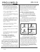
PRO WEL D 1.0 INTRODUCTION Your new stud welding equipment is carefully constructed of the finest components and materials available. Used properly, this equipment will give you years of profitable, efficient service. The system incorporates the latest in engineering advances, for completely reliable end welding of mild steel, stainless steel, aluminum and lead free copper and brass fasteners.
PRO WEL D 5. Don’t operate with worn or poorly connected cables. Don’t operate weld gun with loose cable connections. Inspect all cables frequently for insulation failures, exposed wires, loose connections, and repair as needed. 6. Don’t overload welding cables or continue to operate with hot cables. 7. Don’t weld near flammable materials or liquids, in or near atmospheres, or on ducts carrying explosive gases. 8.
PRO WEL D This technique, when equipment is set up properly, is simple and easily mastered. The same power supply is capable of welding many different sizes and materials of fasteners. If you require assistance in selecting the proper accessories, contact our customer service department or your field representative. 7.
PRO WEL D CD -3 1 2 9.0 WELDING SYSTEM HOOK-UP 9.1 Straight Polarity (Standard Set-Up) (see Figure 2) A. Connect ground cable connector (1A) into camlok (1). The camlok should be connected into the receptacle marked GROUND. Twist until it locks. Attach “C” clamp (2) to the workpiece (5) (CLEANED AREA). B. Connect the gun control cable (3A) into the female receptacle (3). C. Connect the gun weld cable (4A) into the receptacle marked GUN (4). Twist clockwise until it locks. D.
PRO WEL D CD -3 1 2 9.2 Reverse Polarity (Recommended for brass or galvanized) (see Figure 3) A. Connect ground cable connector (1A) into camlok (4). The camlok should be connected into the receptacle marked GUN. Twist until it locks. Attach “C” clamp (2) to the workpiece (5) (CLEANED AREA). B. Connect the gun control cable (3A) into the female receptacle (3). C. Connect the gun weld cable (4A) into the receptacle marked GROUND (1). Twist clockwise until it locks. D. Connect AC power cable to AC outlet.
PRO WEL D CD -3 1 2 9.3 Cuphead and Power Point pin hook-up (see Figure 4) A. Connect ground cable connector (1A) into camlok (1). The camlok should be connected into the receptacle marked CUPHEAD. Twist until it locks. Attach “C” clamp (2) to the workpiece (5) (CLEANED AREA). B. Connect the gun control cable (3A) into the female receptacle (3). C. Connect the gun weld cable (4A) into the receptacle marked GUN (4). Twist clockwise until it locks. D. Connect AC power cable to AC outlet.
PRO WEL D CD -3 1 2 10.0 SYSTEM OPERATION (see Figure 4) 1. The CD-312 is designed for simple, yet precise operation. 2. It has an “ON-OFF” toggle switch/indicator light (1) and a variable voltage control dial (2), a ready indicator light (3), a contact light (4) and a trigger light (5) on the front panel. 3. Before turning the unit “ON”, the voltage control knob (2) should be turned counter-clockwise to the lowest setting. 4.
PRO WEL D Setting the Weld Voltage/Capacitance Slowly turn the voltage control knob clockwise to increase the weld voltage until the indicator knob is pointing at the appropriate number for the particular stud size that you are welding. (See the set up information chart). NOTE: Once the voltage control knob is set to a higher setting, turning it counter-clockwise will NOT reduce the voltage on the capacitor bank, until the toggle switch (1) is turned “OFF” (for approximately 10 seconds).
PRO WEL D CD -3 1 2 11.0 GUN SET-UP 11.1 STANDARD (see Figure 5) The standard gun set-up is used for welding the majority of applications. It consists of the standard adjustable face plate, two legs, a foot, B-collet, stop, and spring for your specific stud size. A step-by-step explanation of the correct way to set-up and operate the standard CD gun. To prepare for stud welding, it is necessary to have the proper accessories for the stud to be welded.
PRO WEL D The gun is now ready to weld. Select the proper setting for the size stud to be welded. Voltage is determined by the weld base diameter. Be sure your power source is set for the proper polarity: straight for steel, reverse for galvanized. 11.2 INSTALLING OR CHANGING COLLETS OR CHUCKS ( The terms collet or chuck are different names for the same device). The collet holds the pin or stud to be welded. It is secured to the gun shaft by two set screws.
PRO WEL D 11.4 TEMPLATE ADAPTER (see Figure 7) The template adapter is used when precise location or positioning of the CD stud is required. It is used with the round faceplate and does not require a footpiece or legs. The adapter is fastened to the faceplate and provides a fixed distance between the collet and work. The plunge is set by using the correct stop in the collet. A template can then be fabricated to enable very precise locating of a particular stud. CD -3 1 2 11.
PRO WEL D Figure 10 Light Duty CD Gun PAGE 12 CD -3 1 2
PRO WEL D CD -3 1 2 11.6 PARTS LIST LIGHT DUTY CD HANDGUN Part No. 300-0100 ITEM PART NO. DESCRIPTION QTY 1 033-384 GUN (CD) REAR CAP MOLDED 1 2 001-800 SPRING MAIN HEAVY SILVER 1 3 033-610 GUN (CD/DA) BEARING ASSEMBLY 1 4 033-799 GUN (CD) SHAFT TUBE 1 5 033-016 HEX HEAD CAP SCREW 3 6 033-382 GUN (CD/DA/FA) TRIGGER SPRING 1 7 049-955 M SCREW SET MS, BRASS PLT 2 8 NOT USED GUN (CD/DA/FA) CABLE CLAMP (ALUM.
PRO WEL D CD -3 1 2 12.0 WELDABLE MATERIAL COMBINATIONS BASE MATERIAL STUD MATERIALS Mild Steel (1008-1018) Mild Steel 1008, 1018 Stainless Steel 304, 305 Brass 65-35, 70-30 Copper, Silicon/Bronze Galvanized Sheet (duct-”Q” Decking Mild Steel 1008-1018 Stainless Steel 304,305 Structural Steel (Must Be Clean) Mild Steel 1008,1018 Stainless Steel 304,305 Brass 65-35, 70-30 Aluminum – Most alloys of the 1100, 3000 and 5000 series.
PRO WEL D CD -3 1 2 13.0 CAUSE OF POOR OR ERRATIC WELDS 12. Incorrect spring. (REPLACE WITH PROPER SPRING) 1. Loose collet. Does not grip stud tightly. (REPLACE) Not enough engagement of stud to collet. (CHANGE STOP) 13. Poor stud quality. 2. Fault or loose ground connection. (REPAIR OR TIGHTEN) 14.0 TROUBLE SHOOTING POOR WELDS 3. Poor surface condition of base material, excessive oil, grease, rust, ect. (CLEAN) 4. Voltage or capacitance setting too low or too high. (ADJUST TO DIAMETER OF STUD) 5.
PRO WEL D CD -3 1 2 15.0 ROUTINE WELDER MAINTENANCE Your CD-312 is designed for long service with minimum care. Ordinary common sense maintenance will keep it operating efficiently. Figure 13 Arc Blow Arc Blow A) Use double grounds. B) Ground too close or not spaced Figure 14 Weld without footpiece 1. Treat the welding, ground, and control cables with respect. Avoid sharp bends and kinks which may break the cables. Don’t use the cables as a “tow line” to move the control.
PRO WEL D CD -3 1 2 16.
PRO WEL D 14 8 9 15 10 CD -3 1 2 17 16 11 12 13 Figure 17 Parts List ITEM 8 9 10 11 12 13 14 15 16 17 PAGE 18 DESCRIPTION Terminal Strip Transformer Dropping Resistor Discharge Resistor Nichrome Resistor PC Board Charging SCR Diode Charging Bridge Safety Discharge SCR PART NUMBER 102-0020 105-0010 112-0042 112-0041 112-0043 600-0007 108-0002 108-0027 108-0017 108-0042
PRO WEL D CD -3 1 2 20 19 21 18 22 23 24 Figure 18 Parts List ITEM 18 19 20 21 22 23 24 DESCRIPTION Power Switch LED Panel Meter LED Red LED Green LED Amber 2-Pole Female Hubbell Female Camlok PART NUMBER 104-0013 103-0002 108-0028 108-0029 108-0030 107-0031 107-0002 PAGE 19
PRO WEL D CD -3 1 2 16.
PRO WEL D CD -3 1 2 17.0 TROUBLE SHOOTING – ELECTRICAL When troubleshooting the power unit/controller (welder), the following precautions must be observed: 1. Welder must be TURNED OFF! 2. Unplug power cable from welder and wait at least two minutes before checking components. 3. The use of a volt/ohmmeter is recommended where any voltage may be present. 4. Use a continuity tester ( or troubleshooting light) for continuity checks only. 5.
PRO WEL D CD -3 1 2 PROBLEM POSSIBLE CAUSE CORRECTIVE ACTION 3. Welder turns on but does not operate A. Ground cable connections not complete. Check for continuity *B. Broken gun control cable or loose wire connection in the plug. Shorted or open trigger switch. Check continuity between pins on control plug while trigger is depressed. Should read continuity. *C. Faulty printed circuit board. Replace with new PC Board. D. Shorted weld SCR.
PRO WEL D CD -3 1 2 18.0 CHECK LIST CD-312 SYSTEM PT. NO. 100-0108 STANDARD CD-312 WELDING SYSTEM COMPLETE WITH B-COLLET GUN AND 25’ #4 GROUND CABLE ITEM 1. 2. 3. 4. 5. DESCRIPTION PART # QTY CD-312 CONTROLLER 110 VAC GUN ASSY. B-COLLET w/INTEGRAL 25 FT.WELD & CONTROL CABLE 2-LEGS, and FOOTPIECE GROUND CABLE #4 X 15’ MANUAL, Operation and Maintenance CD-312 HEX WRENCH SET 200-0012 1 300-0100 125-0100 1 1 1 1 19.0 CHECK LIST CD-312 SYSTEM PT. NO.
MANUFACTURED BY PRO WELD MADE IN THE U.S.A.