
Specifications


CD-312
PRO WELD
5. Don’t operate with worn or poorly con
-
nected cables. Don’t operate weld gun with
loose cable connections. Inspect all cable
s fre
-
quently for insulation failures, exposed wires,
loose connections, and repair as needed.
6. Don’t overload welding cab
les or continue
to operate with hot cables.
7. Don’t weld near flammable materials or liq
-
uids, in or near atmospheres, or o
n ducts carry
-
ing explosive gases.
8. Don’t weld on containers which have held
combustible or flammable materials, or on ma
-
terials which give off flammable or toxic va
-
pors when heated, without proper cleaning,
purging, or inerting.
9. Be sure t
o provide for proper ventilation
when welding in confined spaces.
10. Never look at the electric arc without wear
-
ing protec
tive eye shields.
11. Always use the proper protective clothing,
gloves, ect.
12. Never strike an arc when near a bystander
who is unaware of the dangers of ultraviolet
light on their eyes.
5.0 GENERAL DESCRIPTION
CD
-
312 HEAVY DUTY PORTABLE
CD ST
UD/PIN WELDER
The CD
-
312 portable CD welder is a self co
n-
tained heavy duty capacitor discharge power supply
capable of welding up to 5/16” flanged studs in mild
steel or stainless steel
(3/8” in weld base diameter).
It can weld up to 1/4 flanged studs (5/16” weld base
diameter) in aluminum or brass.
The CD
-312
utilizes a solid state control board
for longer life and has been designed for easy mai
n-
te
nance and field service. This welder uses standard
1
10 volt AC line voltage. The system comes complete
with power cord, weld cables and gun. Just add the
accessories required for t
he stud size to be welded.
This manual should provide all the information r
e-
quired for you to be able to set up, weld, and maintain
the CD
-
312 welding system.
6.0 THE CD WELDING PROCESS
Contact welding
is the simplest and most
co
m
mon method of CD stud welding. Practically
foo
l
proof, it produces no reverse side marking in
most cases and is suitable for most commercial and
industrial applications.
First
, the gun must be set
-up with the proper
accessories for the length and diameter stud you are
going to weld. Refer to the CD Acc
essories Guide
and CD Stud Welding Gun Section for information
on accessories and gun set
-up.
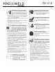
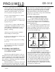
Initial Contact
During Weld
Forced Into Molten Pool
After Weld
1 2
3 4
The stud is first placed in contact with the
base material (SEE FIGURE 1). Verify that the gun is
held perpendicular to the work
. Pulling the trigger
di
scharges the capacitors through the stud which v
a-
porizes the tip. The proper tip design is critical. This
is what determines the length of time of the weld. An
arc is briefly sustained which melts the stud base su
r-
face and the work surface directly underneath the
stud. The spring pressure in the gun then forces the
stud into the molten pool, completing the weld in a
p-
proximately six milliseconds.
(FIGURE 1 CONTACT CD WELD)
PAGE 2