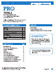
INSTALLATION MANUAL T605-2 Prof Technologies, Inc. S. Glen stone Ave, Suite 2-100 Springfield, MO 65804 Toll-Free: 888-776-1427 Web: www.proliag.com Hours of Operation: M-F 9AM 6PM Eastern EE Description Battery Power Gas or OI Heat Yes Hardwired (Common Wire) Electric Fum ace Yes Hardwired (Common Wire) with Battery Backup Heat Pump (No Aux. or Emergency Heat) Yes Heat Pump {with Aux. or Emergency Heat) No Multi-stage Systems.
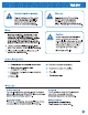
INSTALLATION TIPS Wall locations The thermostat should be installed approximately 4 to 5 feet above the floor. Select an area with average temperature and good air circulation.
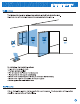
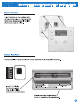
THERMOSTAT QUICK REFERENCE Getting to know your thermostat ® Frag. Tin siren @® Leo Bonk ORF HE Indicates the current room Fan Switch System Switch Easy Change Battery Door Set point Buttons User Buttons OPO, Universal Private Label Badge Removing the private label badge Days of the week and time System operation Indicators: ON will display when the COOL or HEAT is on. NOTE: The compressor delay feature is active if ON is flashing. The compressor will not tum on until the 5 minute delay has elapsed.
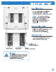
SUB BASE INSTALLATION Caution: Electrical Hazard Failure to disconnect the power before beginning to install this product can cause electrical shock or equipment damage. Mercury Notice: All of our products are mercury free. However, if the product you are replacing contains mercury, dispose of it properly. Your local waste management authority can give you instructions on recycling and proper disposal. For vertical mount put one screw top and one screw bottom.
Caution: Electrical Hazard Failure to disconnect the power before beginning to install this product can cause electrical shock or equipment damage. Warning: All components of the control system and the thermostat installation must conform to Class Il circuits per the NEC Code. Wiring 1. If you are replacing a thermostat, make note of the terminal connections on the thermostat that is being replaced. In some cases the wiring connections will not be color coded.
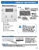
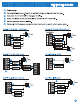
WIRING DIAGRAMS Power supply Set fan operation switch to electric. Typical 1H/1C system: 1 transformer FAN RELAY HEAT RELAY Typical 1H/1C heat pump system Cc 2 L1 Hom RA Sha COMPRESSOR RELAY COOL CHANGE OVER VALVE| HEAT CHANGE OVER VALVE & Typical heat-only system with fan 2 L1 (HoT) & S FAN RELAY HEAT RELAY Use either O or B terminals for changeover valve. Use a small piece of wire (not supplied) to connect W and Y terminals. Factory-installed jumper. Remove only when installing on 2-transformer systems.
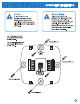
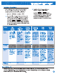
TECHNICIAN SETUP MENU & ee nde Le Gas or Electric Setup i Gas: For systems that control the fan during a call for heat, put the fan operation jumper pin to the GAS position. Electric: The thermostat operation jumper pin should be put in the ELEV position. This setting allows the thermostat to operate the fan when the fan relay is connected to the G terminal. Harnesses Fahrenhelt/Calsius Display Select F or C with the jumper pin on the back of the thermostat. F is for Fahrenheit and C is for Celsius.
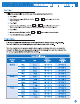
GPA, lel UTI g0 10 10 Technician Setup Menu This thermostat has a technician setup menu 3. Configure the installer options as for easy installer configuration. To setup the desired using the table below. thermostat for your particular application: your PP use the [* Jor keys to 1. Move the SYSTEM switch to OFF. change settings and the Program key to move from one option to the next. Note: Press Hold/Run key when you want to exit the Technician Setup. 2.
MOUNT THERMOSTAT & BATTERY INSTALLATION Mount Thermostat Align the 4 tabs on the sub base with corresponding slots on the back of the thermostat, then push gently until the thermostat snaps in place. Battery installation Battery installation is optional if thermostat is hardwired (C terminal connected). Select HEAT, OFF, or COOL us seeded. Set ANON for Beer oyu Opening Manor 0 ron spec Insert 2 AA Alkaline rv Authenticate sine. Batteries (included). High quality alkaline batteries are recommended.
Set Time Follow the steps below to set the day of the week and current time: 1. Press TIME 2. Day of the week will be flashing. Use the or 1 key to select the current day of the week. 3. Press TIME 4. The current hour is flashing. Use the or [= key to select the current hour. When using 12-hour time, make sure re correct a.m. or p.m. choice is selected. 5. Press TIME &. Minutes are now flashing. Use the or 1 key to select current minutes. 7. Press HOLD/RUN when completed.
PROGRAMMING THE THERMOSTAT You can use the table below to plan your customized program schedule. Programming Table Weekday Woke vay. the fronts Set point Lo EEE ER Looms Es turn Clasp Wake Lava Return Slap Wake Lom Surety Sloop Set Program Schedule To customize your program schedule, follow these steps: Weekday: 1. Select HEAT or COOL from the system switch. Note: You have to program heat and cool each separately. 2. Press PROGRAM 3. Monday-Friday is displayed and WAKE is shown.
SPECIFICATIONS & CONTACT INFORMATION Hold Settings Note: This is a programmable thermostat, and will always be running a programmed schedule. However, it can be overridden with a Temporary or Permanent Hold. TEMPORARY HOLD: With system in Heat or Cool, anytime the set-at temperature is changed with the + or buttons, the thermostat will enter a Temporary Hold. This will be indicated by “HOLD” flashing below the set-at temperature and will remain in this hold until the next programmed time period begins.