
Installation Manual
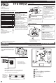

Wiring
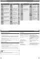
7
Wiring
8
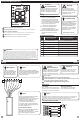
Wiring Technician Setup
11
12
Cooling
Swing
Tech Setup Steps
Adjustment Options Default
LCD Will Show
Room
Temperature
Calibration
This feature allows the installer to
change the calibration of the am-
bient room temperature display.
For example, if the thermostat
reads 70 degrees and you would
like it to read 72 then select +2.
0˚F
4 ˚ - -4 ˚
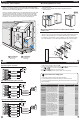
Base Module - PTAC Installation
Side Mount:
Inside PTAC
Housing
Front Mount:
Inside PTAC
Housing
Range between the thermostat and the base module is up to 100 feet
with no obstructions and up to 50 feet through standard building
materials. To optimize the range try placing the base module with no
metal between it and the thermostat.
The base module is designed to be mounted behind the front grille
of a packaged terminal air conditioner (PTAC). Refer to the PTAC
manufacturer’s manual for instruction to remove the front grille.
Check clearance to ensure the t of front grille after base module
installation. See below for a few location recommendations.
When Working With A Vertical Unit
1. Do not mount Module inside the cabinet of the unit, or in a
metal enclosure.
2. Mount on the outside of the unit to maximize wireless
communication.
When Working With A Metal Sleeve Cabinet, Room Cabinet,
or PTAC Cover
1. If cabinet has open bottom, mount the module just inside the
cabinet as close to the open bottom as possible without placing it in
danger of being bumped or touched by furnishings, vaccum, etc.
2. Another good module location would be on the underside of the
top of the cabinet or cover. Directly behind the open Louver/Grill.
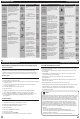
Typical 1H/1C System: 1 Speed Fan
R
Y
W
C
GL
GH
HEAT RELAY
FAN RELAY
COMPRESSOR
RELAY
Typical 1H/1C Heat Pump System: 2 Speed Fan
R
Y
W
C
GL
GH
O/B
COMPRESSOR
RELAY
CHANGE OVER
VALVE
FAN LOW RELAY
FAN HIGH RELAY
C
R
L2
L1
C
R
L2
L1
Typical 2H/1C Heat Pump System: 2 Speed Fan
C
R
L2
L1
COMPRESSOR
RELAY
AUX HEAT
RELAY
FAN LOW RELAY
FAN HIGH RELAY
CHANGE OVER
VALVE
CALIBRATE
The swing setting, often called
“cycle rate”, “dierential” or “antic-
ipation” is adjustable and dictates
how frequenlty the system cycles
on and o. For example: A swing
setting of 0.8˚ will turn the
heating on at approximately 0.8˚
below the setpoint and turn the
heating o at approximately 0.5˚
above the setpoint.
1. Set the thermostat system switch to OFF.
2. To enter Tech Setup Menu, press and hold and together for 3 seconds.
3. Use or to select desired setting for each option.
4. Tap and together to move next option.
5. To exit Tech Setup Menu, move system switch or wait 15 seconds.
Front Panel
Chasis
Sleeve Cabinet
Rough-In
Wall Opening
COOL CHANGE
OVER VALVE
HEAT CHANGE
OVER VALVE
O
B
COOL CHANGE
OVER VALVE
HEAT CHANGE
OVER VALVE
O
B
The swing setting, often called
“cycle rate”, “dierential” or “antic-
ipation” is adjustable and dictates
how frequenlty the system cycles
on and o. For example: A swing
setting of 0.8˚ will turn the
cooling on at approximately 0.8˚
above the setpoint and turn the
cooling o at approximately 0.8˚
below the setpoint.
0.2 ˚ - 2 ˚
0.8˚
Heating
Swing
0.2 ˚ - 2 ˚
0.8˚
0.8
COOL
SWING
0.8
HEAT SWING
1. Tech settings must be transferred to the basemodule.
2. The transfer happens automatically when you exit the tech menu.
3. The Screen will display “TEC SET OK” when the basemodule has received the
new tech settings.
Important Tech Setting Notes