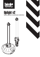
Uplight v2 Safety, operation & maintenance instructions
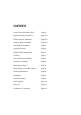
CONTENTS Ground Fault Interrupter (GFI) Page 2 Important Safety Information Page 2-3 Electrical Safety Guidelines Page 3-4 Getting Uplight v2 Started Page 4-5 Self-Righting Properties Page 6 Linking Directions Page 6 Lighting Tube Replacement Page 7 Cleaning Page 7 Service Recommendations Page 7 Questions & Answers Page 8 Replacement Parts Page 8 What Uplight v2 Can Be Used For Page 8 Product Specification Page 8 Guarantee Page 9 Guarantee Policy Page 9 Parts Diagram Page 10
THANK YOU FOR BUYING UPLIGHT v2 You should read the entire operator’s manual before you use your Uplight v2 and you should restrict its use to persons who have read, understood, and who will follow all warnings and instructions contained in this manual. In addition, you should follow all warnings and instructions affixed to your Uplight v2. IMPORTANT SAFETY INFORMATION The safety of this appliance complies with current safety regulations and with applicable directives.
• If the unit is to be positioned horizontally on the ground ensure it does not pose a trip hazard. • If the Uplight v2 is to be used whilst propped against a vertical surface, ensure the unit is positioned on its rubber base. • If Uplight v2 is suspended only use the fixing point on the unit. If the removable eyelets are used ensure they are connected to the correct anchorage points and ensure nothing else is suspended on the unit. • Ensure the mains cable does not present a trip hazard.
INTERNATIONAL MODEL NUMBERS All international model numbers are allocated by individual country. Please refer to the rating plate label on your product for the specific model number. GETTING UPLIGHT v2 STARTED All award-winning UPLIGHT products are designed and manufactured to the highest standards. Used and maintained correctly they will provide dependable long-term operation.
APPLICATIONS OF USE SELF-RIGHTING BASE When used in conjunction with a self-righting base (optional extra) the Uplight v2 has unique self-righting properties from the upright position of up to 45º on the 4’ – 36W model and up to 60º on the 2’ – 18W model. To fit the Uplight v2 to the self righting base locate the Uplight v2 within the base and align the 4 locking tabs, once aligned turn the Uplight v2 through 90º to secure to base. DO NOT relocate the Uplight v2 whilst attached to the self-righting base.
1. Place Uplights in required position. 2. Connect each Uplight together starting with the one farthest from the power supply. Make sure that the power supply power cord(s) is / are out of harm’s way 3. Once all the Uplight’s are connected to each other, plug the host light into the power supply and switch the supply ON. LIGHTING TUBE REPLACEMENT Ensure that only replacement lighting tubes of the correct type are used.
1. How often should I replace the tube? Uplight uses a T8 triphosphor tube with an extended life of 20,000 hours due to the in-built high frequency technology. However, we only recommend replacement of the tube after failure. 2. Is Uplight suitable for indoor or outdoor use? Uplight’s fitted with a 15A plug & socket which are rated to IP44 and are suitable for indoor and outdoor use (IP44 = protected against solid objects over 1mm and water sprayed from all directions - limited ingress permitted). 3.
• • • • Digitally controlled fixed pre-heat time across all ambient temperatures Safety shutdown at end of lamp life Flicker free controlled warm start Automatic restart after lamp change GUARANTEE Thank you for choosing Uplight v2. We are sure that it will provide you with many years of excellent service. Be rest-assured that all Uplight v2 products are engineered and manufactured to ensure the highest standards of reliability and performance during use.
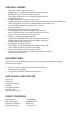
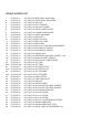
UPLIGHT v2 PARTS LIST 1 2 3 4 5 6 7 8 9 10 11 12 13 14 15 16 17 18 19 20 20A 21 21A 22 22A 23 24 25 26 27 28 29 30 31 32 33 34 35 36 E-UPLV2-01 E-UPLV2-02 E-UPLV2-03 E-UPLV2-04 E-UPLV2-05 E-UPLV2-06 E-UPLV2-07 E-UPLV2-08 E-UPLV2-09 E-UPLV2-10 E-UPLV2-11 E-UPLV2-12 E-UPLV2-13 E-UPLV2-14 E-UPLV2-15 E-UPLV2-16 E-UPLV2-17 E-UPLV2-18 E-UPLV2-19 E-UPLV2-20 E-UPLV2-20A E-UPLV2-21 E-UPLV2-21A E-UPLV2-22 E-UPLV2-22A E-UPLV2-23 E-UPLV2-24 E-UPLV2-25 E-UPLV2-26 E-UPLV2-27 E-UPLV2-28 E-UPLV2-29 E-UPLV2-30 E-UPLV2-31 E
33 15 30 29 2 18 17 28 7 16 UPLIGHT v2 PARTS DIAGRAM 19 22 21 20 9 36 19 6 23 8 13 25 33 31 5 4 11 10 3 14 35 34 14 34 35 27 26 1 32 24 12 32