Operating instructions (ENG) MODELS: APEX GTX - GAS 1.001-139.0 APEX GTX - DIESEL 1.001-140.0 Read these instructions before using the machine.
Machine Data Label Model: Date of Purchase: Serial Number: Dealer: Address: Phone Number: Sales Representative: Overview Welcome…and congratulations on the purchase of your Mobile Cleaning Unit. This instruction manual is a guide for operating and servicing your unit. Read this manual completely before installing or operating this unit. This unit offers you personal convenience. All of your instrumentation and controls have been positioned to give you easy access for operation and daily maintenance.
Table of Contents Machine Data Label . . . . . . . . . . . . . . . . . . . . . . . . . 1 Overview . . . . . . . . . . . . . . . . . . . . . . . . . . . . . . . . . 1 Table of Contents . . . . . . . . . . . . . . . . . . . . . . . . . . . 2 Receiving Your Unit . . . . . . . . . . . . . . . . . . . . . . . . . 4 Acceptance Of Shipment . . . . . . . . . . . . . . . . . . . . . 4 Equipment List: . . . . . . . . . . . . . . . . . . . . . . . . . . . . 4 How to Use This Manual . . . . . . . . . . . . . . . . . .
Table of Contents Parts Options Frame . . . . . . . . . . . . . . . . . . . . . . . . . . . . . . . . . . 58 Side Panel - Right . . . . . . . . . . . . . . . . . . . . . . . . . 62 Side Panel - Left . . . . . . . . . . . . . . . . . . . . . . . . . . 64 Chemical Panel. . . . . . . . . . . . . . . . . . . . . . . . . . . 66 Control Panel - Gas . . . . . . . . . . . . . . . . . . . . . . . 68 Control Panel - Diesel . . . . . . . . . . . . . . . . . . . . . . 70 Control Panel Mounting . . . . . . . . . . . .
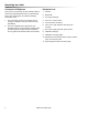
Receiving Your Unit Acceptance Of Shipment Equipment List: Every part of your cleaning unit was carefully checked, tested, and inspected before it left our manufacturing plant. Upon receiving the unit, make the following acceptance check: 1. Console. 1. The unit should not show any outward signs of damage. If damaged, notify the common carrier immediately. 4. 150 ft. of 2" vacuum hose. 2. Check your equipment and packing list.
How to Use This Manual This manual contains the following sections: • • • • • • How to Use This Manual Safety Installation Operations Maintenance & Service Parts List machine. Levels of hazards are identified that could result in product damage, personal injury, or severe injury resulting in death. The INSTALLATION section contains information on how to properly install the unit in your vehicle. The OPERATIONS section is to familiarize the operator with the operation and function of the machine.
Safety IMPORTANT SAFETY INSTRUCTIONS When using this machine, basic precaution must always be followed, including the following: READ ALL INSTRUCTIONS BEFORE USING THIS MACHINE. These symbols mean WARNING or CAUTION. Failure to follow warnings and cautions could result in fatality, personal injury to yourself and/or others, or property damage. Follow these instructions carefully! Read the operator's manual before installing or starting this unit.
Safety DO NOT leave the vehicle engine running while operating this unit. Dangerous Acid, Explosive Gases! Batteries contain sulfuric acid. To prevent acid burns, avoid contact with skin, eyes and clothing. Batteries produce explosive hydrogen gas while being charged. To prevent a fire or explosion, charge batteries only in well ventilated areas. Keep sparks, open flames, and other sources of ignition away from the battery at all times. Keep batteries out of the reach of children.
Safety The following symbols are used throughout this guide as indicated in their descriptions: Hazard Intensity Level There are three levels of hazard intensity identified by signal words - WARNING and CAUTION and FOR SAFETY. The level of hazard intensity is determined by the following definitions: WARNING - Hazards or unsafe practices which COULD result in severe personal injury or death. CAUTION - Hazards or unsafe practices which could result in minor personal injury or product or property damage.
Safety Safety Labels The following WARNING LABELS are found on your cleaning unit. These labels point out important Warnings and Cautions which should be followed at all times. Failure to follow warnings and cautions could result in fatality, personal injury to yourself and/or others, or property damage. Follow these instructions carefully! DO NOT remove these labels. NOTE: If at any time the labels become illegible, promptly replace them.
Installation Dealer Responsibility Your distributor from whom you purchased this mobile cleaning unit is responsible for correct installation of this machine. The dealer is also responsible for initial training of your operators and maintenance personnel in proper operation and maintenance of this unit. Vehicle Requirements 1. The unit should NOT be mounted in any motor vehicle of less than 3/4 ton capacity. DO NOT exceed the vehicle’s axle weight limit.
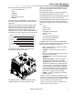
Installation Lifting Unit Onto Vehicle Bolting Down Unit And Waste Tank Since console weighs approximately 910 lbs. pounds, we recommend using a forklift to lift unit onto vehicle. Position forks under unit from front and make CERTAIN that forks are spread to insert into frame slots. NOTE: When positioning waste tank with respect to console, hook up the vacuum hose to waste tank. This will ensure that waste tank is positioned correctly.
Installation Layout with 60 Gallon Waste Tank 1" 3X 2 BACK OF DRIVERS SEAT IN REAR MOST POSITION. 1" 3X 378 11" 2X 116 3" 2X 616 3" 2X 128 2X 17 8" 11" 6816 4" 11" 3X 16 1" 2X 364 5" 2X 168 3" 3X 298 TOP VIEW ENSURE THAT VAC INLETS ON CONSOLE AND WASTE TANK ARE ALIGNED.
Installation Layout with 100 Gallon Waste Tank BACK OF DRIVERS SEAT IN REAR MOST POSITION. 1" 3X 498 1" 3X 2 1" 2X 12 3" 2X 616 2X 123" 8 2X 17 8" 4" 2X 195 8" 11" 6816 11" 3X 16 1" 2X 364 TOP VIEW 3X 293 8" ENSURE THAT VAC INLETS ON CONSOLE AND WASTE TANK ARE ALIGNED.
Installation Waste Tank To Console Connection Fuel Pump Assembly Installation NOTE: Before connecting any hoses to the waste tanks, make certain the hose clamps are on each hose. 1. Connect the section of 3.5" I.D. internal vac hose between the 3.5" dia. vac outlet tube on the waste tank and the vacuum pump relief valve on the console. It may be necessary to cut this hose to fit. Tighten the hose clamps. 2. Connect the 2" I.D. waste removal hose to the 2" dia. tube at the bottom corner of the waste tank.
Installation Van Bulkhead Installation 1. Select a location on the vehicle floor to drill the hole for the bulkhead adapter. This location should be situated in a position that eliminates the possibility of fuel line contact by either the operator(s) or accessories during the working hours or maintenance periods. Make certain that the supplied hoses will reach the location and work with the configuration you choose. 2. Drill a 5/8" (.
Installation Fuel Supply & Return Line Installation GAS MODELS (Underneath Van) 1. Attach the 1/8 NPT x 5/16 Hosebarb 90 degree elbow (86179920) to the bulkhead adapter underneath the van to be used for the fuel supply line. 2. Cut to length the 6' piece of 5/16" 50 PSI fuel hose (86184980) used for the supply line from: a. Bulkhead adapter to the outlet side of the bypass fuel filter (86181620). b. Inlet side of the bypass fuel filter to the discharge side of the fuel pump. c.
Installation Fuel Supply & Return Line Installation DIESEL MODELS (Underneath Van) 1. Attach the 1/8 NPT x 5/16 hosebarb 90 degree elbow (86179920) to the underside of supply line bulkhead (5/16 hosebarb inside the van). 2. Attach the 1/8 NPT x 1/4 hosebarb 90 degree elbow (86179930) to the underside of return fuel bulkhead (3/16 hosebarb inside the van). 3. Cut to different lengths the 6 foot piece of 5/16” 50PSI fuel hose (86282480) for the fuel supply from: a.
Installation Battery Connection Dangerous Acid, Explosive Gases! Batteries contain sulfuric acid. To prevent acid burns, avoid contact with skin, eyes, and clothing. Batteries produce explosive hydrogen gas while being charged. To prevent a fire or explosion, charge batteries only in well-ventilated areas. Keep sparks, open flames, and other sources of ignition away from the battery at all times. Keep batteries out of the reach of children. Remove all jewelry when servicing batteries.
Notes: 86341750 APEX GTX 19
Operations Technical Specifications ITEM Engine speed - GAS MODELS Engine speed - DIESEL MODELS Vacuum pump rpm - GAS MODELS Vacuum pump rpm - DIESEL MODELS DIMENSION/CAPACITY 2740 rpm (high speed) Water Pump ON 850 rpm (idle speed) Water Pump OFF. 2650 rpm (high speed) Water Pump ON 1300 rpm (idle speed) Water Pump OFF.
Operations Chemical Requirements This cleaning unit, due to its chemical injection pump design, can be used with a variety of water-diluted chemical compounds (either acidic or alkaline), depending on the job to be done. However, to obtain optimum results with this unit, we recommend using the PROCHEM line of chemicals. For information on using the cleaning compounds, refer to the chemical manual.
Operations Fuel and Engine Oil Requirements Gas Fuel Use unleaded gasoline ONLY. DO NOT use any gasoline additives. We recommend the use of clean, fresh, unleaded gasoline intended for automotive use. High octane gasoline should NOT be used with the engine on this unit. Engine Oil Use high quality detergent oil of at least API (American Petroleum Institute) service class SF or SG. Select the viscosity based on the air temperature at the time of operation as shown in the following table.
Operations Fuel and Engine Oil Requirements Diesel Use diesel fuel ONLY. NEVER use starting fluid (i.e. ether) to assist in starting engine. Sever engine damage will result. O: Recommended X: Not recommended Fuel Lubricating Oil Class Low-Sulfur High-Sulfur CF 0 0 TBN>10 CF4 0 X - CG4 0 X - Remarks Engine Oil Requirements 1.
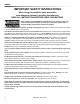
Operations 1 3 2 4 WASTE TANK FULL 14 VACUUM SOLUTION PRESSURE 5 SOLUTION TEMP 6 13 WASTE PUMP OUT AUXILIARY WATER TANK PUMP OFF ON OFF ON 7 CHOKE SOLUTION PUMP OFF 12 11 OVERRIDE TO START ENGINE ON IGNITION 8 THROTTLE OFF RUN START 10 HOURS MAIN ENGINE PUMP OUT SOLUTION PUMP 9 Components - Upper Control Panel GAS 1. Waste Tank Full Indicator Light 2. Panel Light This indicator light is activated when the waste tank is full.
Operations 4. Solution Pressure Gauge 10. Hour Meter This gauge registers the amount of pressure in the system. The hour meter records the number of hours the unit has run. This serves as a time recorder for servicing the machine. 5. Solution Temperature Gauge This gauge measures the temperature of the cleaning solution as it exits the machine. 6. Waste Pumpout This switch actuates the optional waste pumpout. 7. Choke 11. Ignition Switch The ignition switch controls the power for the machine.
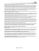
Operations 1 3 2 4 GLOW PLUG WASTE TANK FULL 14 VACUUM CHECK ENGINE 5 SOLUTION PRESSURE 6 SOLUTION TEMP 7 13 WASTE PUMP OUT AUXILIARY WATER TANK PUMP OFF OFF ON ON 8 SOLUTION PUMP OFF ON 12 IGNITION GLOW PLUG THROTTLE OFF RUN 9 START 11 HOURS MAIN ENGINE PUMP OUT SOLUTION PUMP 10 Components - Upper Control Panel DIESEL 2. Glow Plug Indicator Light 1. Waste Tank Full Indicator Light This indicator light is activated when the waste tank is full.
Operations 4. Engine High Temperature / Low Oil Pressure Shutdown Indicator This light when activated signals an engine over heat or a low oil pressure condition. When this occurs, troubleshooting is required. 10. Circuit Breakers These serve to protect the circuits from electrical spikes and over loads and protects wires from damage and fire. 11. Hour Meter 5. Solution Pressure Gauge This gauge registers the amount of pressure in the system. The hour meter records the number of hours the unit has run.
Operations See Upper Panel Components 18 17 16 15 1 14 SOLUTION PRESSURE REGULATOR TEMPERATURE BALANCE ORIFICE CHEMICAL CHECK VALVE 13 BALANCE ORIFICE ON/OFF VALVE 12 SOLUTION TEMPERATURE CONTROL VALVE SOLUTION SCREEN 2 WARM CONDENSED OPERATING INSTRUCTIONS STARTING 11 SOLUTION OUTLETS SHUTDOWN AND DAILY MAINTENANCE 10 9 8 7 5 6 Components The lubrication cup allows lubricant spray to reach the vacuum blower. The vacuum inlets serve as connecting points for vacuum hoses. 28 3 3.
Operations 5. Solution Outlets The solution outlets are the connecting point for the high pressure solution hoses. These outlets are quick disconnects that allow hoses to be plugged into the unit. 13. Water Inlet This quick connect allows the water supply hose to be connected to the unit. 14. Solution Pressure Regulator 6. Solution Screen The solution screen is located on the front of the machine.
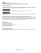
Operations Water Pumping And Heat Transfer System Cold water enters the console through the water inlet. When the water box is full the valve will automatically shut off. Water then flows from the water box, through the strainer, into the solution pump. The water is pumped to the pressure regulator manifold, which provides and maintains the desired pressure setting. The pressure regulator manifold includes a pulse hose which helps reduce pressure spikes from the pump.
Operations SINGLE SYSTEM WATER FLOW DIAGRAM LOW PRESSURE = COLD WATER = WARM WATER WASTE TANK = HOT WATER VACUUM EXHAUST HEAT EXCHANGERS THERMO RELIEF WATER BOX HELI-COIL ENGINE COOLANT HEAT EXCHANGER ENGINE SOLUTION PUMP ENGINE THERMOSTAT RADIATOR TO PRESSURE GUAGE PULSE HOSE MANIFOLD WATER INLET LOW PRESSURE REGULATOR WARM WATER OUTLET TEMPERATURE BALANCE ORIFICE VALVE OUTLET CHECK VALVE OUTLET Y-STRAINER CHEMICAL INJECTION SOLUTION OUTLETS SOLUTION OUTLET MANIFOLD 86341750 APEX GTX 31
Operations Chemical Injection System The chemical injection system is unique in that it utilizes the pressure spikes generated by the highpressure solution pump to move chemical into the main solution stream. The high pressure spikes move the diaphragm in the chemical pulse pump forcing small amounts of liquid chemical to be moved in a single direction of flow with the aid of two check valves. The chemical is drawn from the container, and through the flow meter, which indicates rate of flow.
Operations Vacuum System The engine turning a vacuum pump generates vacuum. The air is channeled in one side of the vacuum pump, compressed and discharged on the opposite side, creating airflow. The movement of air is used to do the work necessary for the extraction process. A vacuum nozzle applied to the carpet surface removes moisture, dirt and spent chemicals. These elements are conveyed back to a separating tank utilizing hoses and the force of air.
Operations Pre-Run Inspection / Setup High Pressure Solution Hose NOTE: Operation of this unit is simple. However, only trained personnel should proceed. Operate this unit and equipment only in a well-ventilated area. Exhaust fumes contain carbon monoxide which is an odorless and deadly poison that can cause severe injury or fatality. DO NOT operate this unit where the exhaust may enter any building doorway, window, vent, or opening of any type.
Operations Priming the Chemical Pump 1. Fill chemical container and inspect chemical strainer. 2. Insert chemical inlet tubing into chemical container. 3. To start engine: NEVER dispose of waste in storm drains, waterways, or on ground areas. Always dispose of waste in accordance with Local, State, and Federal laws. Waste Pumpout (Optional) GAS MODELS - Pull out engine choke, turn solution pump switch to override, and turn ignition key to start. Push in engine choke after engine has started.
Operations Upholstery Cleaning De-Flooding Operations Upholstery tool, (See Options section) De-flooding operations involve removal of water from carpet and flooring. This differs from normal cleaning operations in that no water or solution is required. An automatic waste pump-out is highly recommended for all de-flooding operations due to the large amount of water removal often required. 1.
Operations Winterizing Your Unit 1. Shut off the water supply. Disconnect the water inlet hose from the front of your console. 2. Start the unit and turn solution pump on. Open the tool valve until water pressure drops. 3. Turn off the solution pump. Fill the water box with approximately two gallons of 100% glycol base anti-freeze. 4. Turn the solution pump ON. 5. Connect all solution pressure hoses and tools that may have water in them. 6.
Operations Removing Anti-Freeze From the Unit 2. Start unit turn on pump. 5. Place the chemical prime hose into the approved container. Submerge the chemical inlet hose in water. Turn the chemical valve to the PRIME position until clear water comes through the prime hose, and then remove the prime hose from the container. 3. Connect all solution hoses and any tools which require purging of anti-freeze to the solution outlet connection(s). 6. Turn the chemical valve to the ON (CHEMICAL) position.
Maintenance Service Schedule Engine Daily Check engine oil level. *** Fill to proper level Engine Daily Check coolant level in overflow bottle Vacuum Pump Daily Spray water displacing lubricant in lubrication cup at front of console for 5 sec. Solution Pump Daily Check oil level.
Maintenance Service Schedule Vacuum Exhaust Heat Exchanger Solution Pump Pulley Set Screws, Hub Cap Screws, & Solution Pump Clutch Shaft Bolts Drive Pulley Drive Pulley Drive Belts Drive Belts Chemical Pump & Check Valves Engine Check Valve (Solution Outlet) Vacuum Pump Engine Engine Waste Tank Filters/Strainers Engine Battery Engine 500 hrs 500 hrs Inspect cores and remove debris. (GAS MODELS ONLY) Change oil** 500 hrs Check for proper torque values.
Maintenance All Machines Heat Exchanger System Maintenance Key Checkpoints Note: Initiation of a planned preventative maintenance program will assure that your unit has optimum performance, a long operating life, and a minimal amount of "down" time. Engine Coolant System (Radiator) Maintenance Your engine radiator coolant system is an important part of the power plant operation.
Maintenance Engine - Gas 3. Re-torque the manifold and exhaust tube nuts, cylinder head bolts, and carburetor attaching nuts after the first 200 hours of use. DO NOT service this unit while it is running. The high-speed mechanical parts as well as high temperature components may result in severe injury, severed limbs, or fatality. NOTE: Use the hour meter as a guide for coordinating the maintenance schedule. (Refer to engine manufacturer's manual for specific maintenance instructions) 1.
Maintenance Engine - Diesel Lubricating Oil DO NOT service this unit while it is running. The high-speed mechanical parts as well as high temperature components may result in severe injury, severed limbs, or fatality. NOTE: Use the hour meter as a guide for coordinating the maintenance schedule. (Refer to engine manufacturer’s manual for specific maintenance instructions) 1. Check the engine oil level daily. Make certain that proper oil level is maintained. NEVER overfill. 2.
Maintenance All Machines Vacuum Pump Refer to the Vacuum Pump Operation and Service Manual for specific instructions. Lubrication: We recommend that you use AEON PDXD Synthetic Blower Lubricant in both ends of the vacuum pump for all operating temperatures. AEON PD-XD is formulated especially for positive displacement blower service to provide maximum blower protection at any temperature. One filling of AEON PDXD will last many times longer than a premium mineral oil.
Maintenance Vacuum Inlet Filter (In Waste Tank) Solution Pump The vacuum filter in the waste tank should be removed and cleaned daily. If this is done, the filter will last for a long period of time. 1. Check the crankcase oil level daily to assure the proper level. Use the illustration as a guide when checking the oil level. If the level has dropped, check for the source of leakage and repair.
Maintenance Solution Pump Drive Belt Waste Tank Strainer Basket To tighten the solution pump belt: The strainer basket located inside the waste tank should be removed and cleaned whenever it is full of debris. This should be done on at the end of each job. 1. Loosen the nuts which hold the solution pump mount to base. 2. Adjust the position of the belt tension adjusting bolt until the proper belt tension is achieved. (1/2" deflection in the center of the belt, halfway between the pulleys). 3.
Maintenance Check Valve (Outlet) Vacuum Hoses Inspect the check valve when rebuilding the chemical pump or as needed. Remove and disassemble the check valve. Check the Teflon seat for debris or abnormal wear. Clean or replace seat if needed. To assure maximum hose life, we recommend that the hoses be washed out with clean water at the end of each working day. NOTE: Improper seating of the check valve poppet, damaged spring, or o-rings will cause poor operation of the chemical system.
Maintenance Engine Coolant Replacement General Service Adjustments The coolant should be replaced every year. This coolant is an integral part of the heating system and needs to be maintained as any other working part of the system. We recommend that this procedure be accomplished by the following steps. USE EXTREME CAUTION The high-speed mechanical parts as well as high temperature components may result in severe injury, severed limbs, or fatality. Draining Coolant: Engine Speed 1.
Maintenance High Altitude Operations - Gas Check Valve (Solution Outlet) Altitude compensation kit is applied for EPA and CARB certified engines only. EPA and CARB emission regulations require the ultimate users of non-road SI engines, as their obligation, to adjust the emissions by installing the appropriate genuine altitude compensation kit. The engine manufacturer must provide such kit when the engine is operated at an altitude that exceeds the standard level, as guaranteed by the engine manufacturer.
Maintenance Water Box 1. Check inlet strainer for debris and blockage. A blocked strainer could damage the solution pump if water flow is restricted. 2. Inspect water box float valve for freedom of movement and water leaking past valve. Chemical Pump Packing Nut Adjustments For Chemical Valves Examine the packing nut on all chemical valves for proper tension every 200 hours. When turning the knob, there should be a small amount of resistance. If not, slightly tighten the packing nut. DO NOT over tighten.
Maintenance Pressure Regulator The pressure regulator serves to maintain water pressure at a preset point and to bypass water back to the water box. To adjust: 1. With your unit running, close the cleaning tool valve. Check the pressure gauge. Open the tool valve. We recommend setting the pressure regulator so that the pressure gauge reads 450 PSI with the tool valve closed. When the tool valve is opened, there is an approximate drop of 100 PSI in pressure.
Maintenance Troubleshooting Problem Loss of solution pump pressure. With the cleaning tool open, the solution pressure gauge reads below the normal operating pressure. Loss of solution volume at cleaning tool orifice. Solution gauge reads normal. 52 Cause Solution Water supply is turned off or the float valve is stuck or improperly adjusted. Turn the water supply on or up. Check for kinks in the water supply hose. Examine the float valve and adjust or replace.
Maintenance Problem Cause Vacuum gauge is giving an improper reading. Loss of vacuum While cleaning, the vacuum is not up to specification. Engine RPM is normal. Excessive vacuum Loss of chemical With the cleaning tool valve open, no chemical Chemical flow meter indicates flow with the tool valve closed Vacuum hose(s) is damaged, causing a suction leak. Waste tank gaskets not sealing properly, not positioned properly Plugged vacuum hose or vacuum plumbing between vacuum inlet and strainer basket.
Maintenance Troubleshooting Continued Problem Solution pump does not engage Cause Solution Solution pump circuit breaker has been tripped Check the solution pump circuit breaker on the control panel. Press the circuit breaker reset button. Defective electrical connection in the console wiring or defective switch. Examine switch, electrical connections, and wiring. Repair any defective connections. If there is power going to the switch but not going out, replace the defective switch.
Maintenance Problem Engine stops running. While doing normal cleaning, the engine stops running. Excessive heating Cause Solution Engine is out of fuel Add fuel to the fuel tank. Waste tank is full Empty waste tank. Main or engine circuit breaker on the control panel has been tripped. After inspecting the unit to determine the cause of the tripped circuit breaker, press the reset button. Engine coolant temperature has exceeded 240°F, triggering the high temperature switch to shut the unit down.
Notes: 56 86341750 APEX GTX
Parts PARTS 86341750 APEX GTX 57
Frame 5 19 6 14 11 17 14 7 15 14 DIESEL ONLY 22 11 21 20 14 11 17 23 11 14 16 14 19 14 11 17 4 7 14 17 11 12 25 26 24 13 14 19 15 14 19 18 19 14 10 1 2 3A 3B 58 9 86341750 APEX GTX 8
Frame REF PART NO.
Frame 4 1 14 12 17 2 11 11 8 10 7 6 12 17 3 20 5 15 12 17 15 13 18 16 19 60 9 86341750 APEX GTX 7
Frame REF PART NO.
Side Panel - Right 4 3 2 1 62 86341750 APEX GTX
Side Panel - Right REF PART NO. QTY 1 2 3 4 86330040 86180370 86180700 86178700 1 1 2 1 DESCRIPTION SERIAL NO.
Side Panel - Left PART OF 11 6 TO WATER BOX 10 FROM WATER BOX 13 11 4 TO WASTE TANK 7 8 1 3 9 12 5 2 14 64 86341750 APEX GTX
Side Panel - Left REF PART NO. QTY 1 2 3 4 5 6 7 8 9 10 11 12 13 14 86195230 86195180 86188180 86188080 86186470 86181400 86181360 86179710 86177220 86177060 86173640 86173530 86353210 86181410 1 1 1 1 1 1 1 1 1 2 1 1 1 1 DESCRIPTION SERIAL NO. FROM NOTES VLV, BALL 1/2FP BS VALVE, BALL 1.5 FNPT NIP, 1/2 X CL NIP,3/8 HX BR LABEL, VAC/WTR INLET FTTG, BRB 3/8P x 5/8H BR FTTG, BRB 1/2P X 5/8H BR DSC, 3/8F X 3/8FP CLMP, HOS#32 1.5625/2.
Chemical Panel 14 10 5 2 1 15 4 6 8 11 12 7 16 9 66 17 3 13 86341750 APEX GTX
Chemical Panel REF PART NO. QTY 1 2 3 4 5 6 7 8 9 10 11 12 13 14 15 16 17 86273180 86270330 86176990 86188000 86194160 86177660 86181300 86195050 86181170 86247720 86274290 86279470 86189050 86195160 86297070 86324090 86324460 2 2 2 1 1 4 2 1 1 2 2 2 2 1 1 1 1 DESCRIPTION SERIAL NO.
Control Panel - Gas 25 7 22 21 14 11 13 10 6 8 9 15 4 16 17 19 26 3 20 5 18 12 12 2 24 27 23 1 68 5 86341750 APEX GTX
Control Panel - Gas REF PART NO.
Control Panel - Diesel 5 7 9 3 27 30 25 24 13 16 15 8 12 10 17 6 11 20 18 2 19 22 28 29 4 23 21 14 29 14 26 1 70 86341750 APEX GTX
Control Panel - Diesel REF PART NO.
Control Panel Mounting 3 1 2 72 86341750 APEX GTX
Control Panel Mounting REF PART NO. QTY 1 2 3 86273180 86270330 86189050 4 4 4 DESCRIPTION SERIAL NO.
Engine - Gas 3 19 20 14 12 16 5 28 9 11 29 2 22 13 6 TO Y-ADAPTER 17 23 19 26 31 11 30 25 TO HEAT EXCHANGER 24 7 4 1 11 8 10 18 15 74 21 86341750 APEX GTX 27
Engine - Gas REF PART NO.
Engine - Diesel 4 21 17 15 22 8 18 29 12 3 19 30 9 6 16 21 27 23 24 19 1 14 26 10 25 5 TO HEAT EXCHANGER 2 28 20 13 76 11 7 86341750 APEX GTX
Engine - Diesel REF PART NO.
Engine Mounting 5 6 5 6 7 9 8 3 5 6 7 4 78 86341750 APEX GTX 2 1
Engine Mounting REF PART NO. QTY 1 2 3 4 5 6 7 8 9 86274750 86010780 86046140 86046130 86010720 86175450 86176050 86051630 86046000 1 1 1 1 8 8 3 1 1 DESCRIPTION SERIAL NO. FROM NOTES SCR, 1/4-20 X 3/4 HHCS WASHER, 1/4 SPLIT BRKT, RIGHT ENG MTG BRKT, LEFT ENG MTG WASHER, M10 X 30 PLTD BOLT, M10-1.50X20,CLASS 8.
Engine Mounting GAS ENGINES ONLY 20 8 23 8 10 3 1 15 8 4 6 13 14 11A 11B 2 19 GAS 22 2 DIESEL 12 5 2 16 17 1 18 21 9 18 80 86341750 APEX GTX 7
Engine Mounting REF PART NO. QTY 1 2 3 4 5 6 7 8 9 10 11A 11B 12 13 14 15 16 17 18 19 20 21 22 23 - 86279510 86278830 86277770 86275570 86274910 86273830 86274000 86270330 86233410 86185600 86185050 86185060 86136640 86177250 86177220 86173910 86279130 86137280 86005770 86005750 86005680 86177430 86274690 86271940 86177390 86177400 86181190 8 4 1 2 1 2 3 5 1 1 1 1 1 1 1 1 1 1 6 2 2 1 1 2 1 1 1 DESCRIPTION WASHER, 3/8 FLAT WASHER, 5/16 FLAT PLTD SCR, 3/8-16 X 4.00 ALL THD SCR, 1/4-20 X 1.
Coolant System 17 5 8 11 3 10 14 12 TO THERMOSTAT HOUSING 11 16 4 TO LOWER FITTING ON HELICOIL 16 7 5 12 FROM ENGINE 10 9 6 13 3 6 15 2 82 86341750 APEX GTX 1
Coolant System REF PART NO. QTY 1 2 3 4 5 6 7 8 9 10 11 12 13 14 15 16 17 86334370 86278380 86274750 86177090 86270330 86195590 86191530 86189050 86177310 86177020 86176990 86175820 86173590 86010780 86010730 86046200 86273180 1 2 6 1 6 4 1 2 3 2 2 1 1 4 2 1 2 DESCRIPTION PNL, FRONT RAD CLOSEOUT SHOULDER BOLT, 5/8 OD X 2.25 L SCR, 1/4-20 X 3/4 HHCS CLAMP, CABLE 1/2I.D. 1/4BLT FLATWASHER, 1/4 WASHER, RUBBER, .
Vacuum Pump 84 86341750 APEX GTX
Vacuum Pump REF PART NO.
Solution Pump 17 39 38 37 6 12 10 31 8 11 5 9 15 20 1 16 19 32 29 24 25 13 36 35 28 27 33 25 24 23 34 1 21 2 22 14 4 3 86 86341750 APEX GTX 7 18 30
Solution Pump REF PART NO.
Solution Pump 88 86341750 APEX GTX
Solution Pump REF PART NO.
Heat Exchanger - Exhaust - Gas 36 37 34 38 8 33 39 20 35 32 17 28 25 26 27 4 12 11 28 20 9 30 3 19 22 21 29 22 31 10 13 17 28 6 21 28 17 21 30 24 2 7 5 21 30 14 90 86341750 APEX GTX 15 16 1 23 15 18
Heat Exchanger - Exhaust - Gas REF PART NO.
Heat Exchanger - Exhaust - Diesel 34 33 8 20 32 4 17 28 25 26 27 12 11 28 20 9 30 3 19 22 21 29 22 31 10 13 17 28 6 21 28 17 21 30 24 2 7 5 21 30 14 92 86341750 APEX GTX 15 16 1 23 15 18
Heat Exchanger - Exhaust - Diesel REF PART NO.
Heat Exchanger-Cores 14 4 7 3 1 10 10 2 1 9 6 9 8 13 11 12 5 6 9 94 13 9 86341750 APEX GTX 10 10 9 9
Heat Exchanger-Cores REF PART NO. QTY 1 2 3 4 5 6 7 8 9 10 11 12 13 14 86318840 86313690 86274750 86270330 86182190 86181400 86010780 86180240 86180220 86177700 86177060 86051230 86051220 86043150 1 3 18 18 6 2 18 1 6 4 2 1 2 2 DESCRIPTION SERIAL NO.
Heat Exchanger Mounting 6 4 SEE ENGINE MOUNTING 4 2 1 6 2 5 4 4 5 3 1 4 4 96 3 86341750 APEX GTX
Heat Exchanger Mounting REF PART NO. QTY 1 2 3 4 5 6 86005770 86325250 86274000 86279510 86010790 86006740 2 2 3 8 4 3 DESCRIPTION SERIAL NO. FROM NOTES NUT, 3/8-16 HEX NYLOCK BRKT, HE BOX SUPPORT, PGT SCR, 3/8-16 X 3 HHCS GR5 WASHER, 3/8 X 1 FLAT NP WASHER, 3/8 SPLIT SCR, 3/8-16 X 1.
Helicoil 6 5 4 1 9 10 13 12 11 3 2 8 98 5 86341750 APEX GTX 7
Helicoil REF PART NO. QTY DESCRIPTION 1 86344980 1 O-RING, HELICOIL 2 3 4 5 6 7 8 9 10 11 86342090 86342080 86342070 86278910 86276430 86274010 86271930 86191900 86188980 86182370 1 1 1 24 8 4 12 2 2 2 BRKT, HELICOIL MTG SHELL, FRONT, HELICOIL SHELL, REAR, HELICOIL WASHER, 3/8 X 7/8 FLAT SS SCR, 3/8-16 X 1.75 HHCS SS SCR, 3/8-16 X 2.
Helicoil Mounting 1 10 2 8 FROM THERMOSTAT ADAPTER ON ENGINE 11 6 TO SECOND HEAT EXCHANGER 3 4 5 7 6 4 3 TO PRESSURE REGULATOR TO ENGINE "Y" ADAPTER 100 86341750 APEX GTX 8 9
Helicoil Mounting REF PART NO. QTY 1 2 3 4 5 6 7 8 9 10 11 86177560 86342100 86177310 86181420 86180260 86180430 86180000 86010790 86279510 86006740 86233410 1 1 2 2 1 2 1 2 2 2 1 DESCRIPTION SERIAL NO. FROM NOTES: COCK, DRN 1/4P X 1/4 HOSE ELL ASSEMBLY, HELICOIL CLMP, HOSE #16 1-1/2 MIN 1-3/4 FTTG, BRB 3/4PX1H BR ELL, 3/4 ST BR ELL, 3/4PX1/2T BR ELBOW, 3/4" 45 DEG BRASS ST WASHER, 3/8 SPLIT LOCK PLTD WASHER, 3/8 FLAT SCREW 3/8-16 X 1" HHCS GR5 PLT DL CLAMP, 3/4 DIA CUSHION .
Solution Outlet 24 25 26 27 28 29 30 22 23 13 9 11 6 4 12 7 19 18 1 3 5 17 16 102 14 10 20 86341750 APEX GTX 15 12 8 2 21
Solution Outlet REF PART NO.
Water Box 6 22 15 20 27 13 11 25 16 18 13 18 21 FROM WATER INLET 10 7 21 17 5 TO WARM WATER OUTLET 10 9 13 18 TO TOP OF COPPER HEATER CORE 12 19 OVERFLOW HOSE 16 14 8 23 TO SOLUTION PUMP 26 104 86341750 APEX GTX 4 2
Water Box REF PART NO. QTY 1 2 3 4 5 6 7 8 9 10 11 12 13 14 15 16 17 18 19 20 21 22 23 24 25 26 27 86348200 86273330 86270770 86270330 86195340 86195060 86194120 86193440 86190480 86188180 86031950 86181370 86181360 86180420 86180250 86180170 86177660 86177060 86177020 86176400 86175870 86192380 86057160 86056660 86010660 86005680 86189010 1 2 2 4 1 1 1 2 1 3 1 1 4 1 1 2 1 4 1 1 2 1 1 1 2 2 1 DESCRIPTION SERIAL NO. FROM NOTES BALL, 4" DIA X 5"L, WHITE FLOAT SCR, CAP 1/4-20 X 2.
Pressure Regulator 3 20 4 2 3 19 13 18 10 7 14 1 6 9 12 16 8 106 5 15 11 17 TO COPPER HEATER CORE 86341750 APEX GTX
Pressure Regulator REF PART NO. QTY 1 2 3 4 5 6 7 8 9 10 11 12 13 14 15 16 17 18 19 20 21 86326090 86273330 86270330 86233390 86191660 86190520 86190480 86188390 86187770 86185180 86181400 86180450 86180360 86180240 86180210 86177700 86177060 86175920 86010780 86005680 86374090 1 5 8 3 1 1 1 1 1 1 1 1 1 1 1 1 1 1 2 3 1 DESCRIPTION SERIAL NO. FROM NOTES BUSHING, 1/2MPT X 3/8FPT BR SCR, CAP 1/4-20 X 2.
100 Gallon Waste Tank 15 22 7 PART OF 4 3 12 8 5 11 13 9 6 21 16 19 TO VACUUM PUMP 10 7 4 1 20 2 18 17 14 108 86341750 APEX GTX
100 Gallon Waste Tank REF PART NO. QTY 1 2 3 4 5 6 7 8 9 10 11 12 13 14 15 16 17 18 19 20 21 22 - 98409640 86190530 86180340 86193540 86186860 86043190 86005810 86273020 86273810 86010630 86193870 86202240 86325770 86318560 86325650 86325720 86328460 86323580 86323700 86177010 86272720 86202180 86350770 86264850 1 2 2 1 2 1 8 8 8 8 1 8 1 1 1 1 1 1 1 1 1 1 1 - DESCRIPTION ASSY, 100G WST TNK, APEX PC PLUG, 1-1/4 HXHD PVC ELL, 1/4P X 1/4T BR STRNR, WST TNK, RECT, 1.
60 Gallon Waste Tank 15 22 7 PART OF 4 12 8 3 5 11 13 9 21 6 16 7 19 TO VACUUM PUMP 4 20 18 2 10 1 17 14 110 86341750 APEX GTX
60 Gallon Waste Tank REF PART NO. QTY 1 2 3 4 5 6 7 8 9 10 11 12 13 14 15 16 17 18 19 20 21 22 - 98409630 86190530 86180340 86193540 86186860 86043190 86005810 86273020 86273810 86010630 86193870 86202240 86318530 86318560 86320940 86320990 86328460 86323580 86323700 86177010 86272720 86202180 86350790 86264850 1 2 2 1 2 1 8 8 8 8 1 8 1 1 1 1 1 1 1 1 1 1 1 - DESCRIPTION ASSY, 60G WST TNK, APEX PC PLUG, 1-1/4 HXHD PVC ELL, 1/4P X 1/4T BR STRNR, WST TNK, RECT, 1.
Fuel Pump - Gas 17 12 TO CONSOLE 13 20 THROUGH VEHICLE FLOOR 20 5 4 24 15 15 14 USE AS NEEDED 16 11 1 1 23 6 2 16 21 8 8 2 1 7 3 18 112 19 23 9 FROM VEHICLE FUEL SUPPLY 17 RETURN TO VEHICLE FUEL SUPPLY MOUNT TO VEHICLE FRAME 16 12 22 86341750 APEX GTX 10
Fuel Pump - Gas REF PART NO. QTY 1 2 3 4 5 6 7 8 9 10 11 12 13 14 15 16 17 18 19 20 21 22 23 24 - 86010630 86173340 86175970 86176930 86177880 86181300 86191420 86273780 86335230 86335240 86005810 86175850 86175980 86177370 86177390 86177400 86179920 86180960 86181620 86182460 86273810 86282410 86184980 86339630 86282810 86265730 86273290 14 6 2 1 1 2 1 6 1 1 4 1 1 4 2 7 2 1 1 2 4 1 1 1 2 10 4 DESCRIPTION SERIAL NO.
Fuel Pump - Diesel THROUGH VEHICLE FLOOR 3/16" HOSE 19 17 23 12 20 TO CONSOLE 13 20 25 15 12 4 22 17 5 MOUNT TO VEHICLE FRAME 24 11 15 14 USE AS NEEDED 1 23 9 RETURN TO VEHICLE FUEL SUPPLY 1 16 16 21 8 8 2 1 2 23 FROM VEHICLE FUEL SUPPLY 6 7 3 18 114 86341750 APEX GTX 10
Fuel Pump - Diesel REF PART NO. QTY 1 2 3 4 5 6 7 8 9 10 11 12 13 14 15 16 17 18 19 20 21 22 23 24 25 - 86010630 86173340 86175970 86176930 86177880 86181300 86191420 86273780 86335230 86335240 86005810 86175850 86175980 86177370 86177390 86177400 86179920 86180960 86185080 86182460 86273810 86282410 86282480 86339630 86179930 86282810 86265730 86273290 14 6 2 1 1 2 1 6 1 1 4 2 1 4 6 10 2 1 1 4 4 1 1 1 1 2 10 4 DESCRIPTION SERIAL NO.
Battery Floor Mount 2 1 10 3 4 5 9 6 7 8 116 86341750 APEX GTX
Battery Floor Mount REF PART NO. QTY DESCRIPTION - 86030550 1 KIT, BAT FLR MTG TM 1 2 3 4 5 6 7 8 9 10 86273780 86005680 86174580 86012060 86273190 86270330 86010780 86270770 86309890 86011470 2 2 1 1 4 8 8 8 1 4 SCR, 1/4-20 X 3/4 HHCS SS NP NUT, 1/4-20 HEX NYLOCK BATTERY BOX, BATTERY, MODIFIED SCR, 1/4-20 X 1-1/2 HXHD FLATWASHER, 1/4 WASHER, 1/4 SPLIT LOCK PLTD NUT, 1/4-20 HEX BRKT, BATTERY BOX MTG BOLT, ELEVATOR, 1/4-20 X 1 86341750 APEX GTX SERIAL NO.
Chemical Jug Floor Mount 5 2 4 1 6 3 118 86341750 APEX GTX
Chemical Jug Floor Mount REF PART NO. QTY 1 2 3 4 5 6 86298250 86273190 86270770 86270330 86185720 86010780 1 4 4 4 1 4 DESCRIPTION SERIAL NO.
Hose Diagram - Gas 120 86341750 APEX GTX
Hose Diagram - Diesel 86341750 APEX GTX 121
Wiring Diagram - Gas INSTRUMENT LIGHT KIT HOUR METER + BLU 16Ga A B RED WASTE TANK FULL LIGHT WHT/GRN 16Ga A B C (LOCATED ON THERMOSTAT ADAPTER MANIFOLD) - AMBER CHECK ENGINE LIGHT BLK 16Ga + - PUMPOUT SWITCH BLK 16Ga + - AUXILIARY WATER TANK PUMP SWITCH N.C. N.C. N.O. S G I KUBOTA SUPPLIED HARNESS TEMP GAUGE F M M F FUEL SOLENOID 30 AMP TEMP/ OIL PRESS OVERRIDE SW & (2) N.O. CONTACT BLOCKS REAR OF CONNECTOR 15 AMP KUBOTA ENGINE N.O. 20 AMP WHT COM N.O. BLK N.C.
Wiring Diagram - Diesel 86341750 APEX GTX 123
Notes: 124 86341750 APEX GTX
Options OPTIONS 86341750 APEX GTX 125
Hose Accessories 1 23 2 3 22 2 7 4 5 10 6 11 12 9 8 14 13 17 18 19 15 21 20 16 126 86341750 APEX GTX
Hose Accessories REF PART NO. 1 2 3 4 5 6 7 8 9 10 11 12 13 14 15 16 17 18 19 20 21 22 23 86180980 86178640 86184510 86247680 86002450 86005580 86184530 86184520 86182800 86194990 86189240 86189250 86188210 86184570 86179630 86184620 86002450 86184520 86182800 86005580 86184540 86328140 86328150 QTY 1 2 1 1 1 1 1 1 2 1 2 2 1 1 1 1 1 1 2 1 1 1 1 DESCRIPTION SERIAL NO.
Exhaust - Optional 5 1 4 3 2 128 86341750 APEX GTX
Exhaust - Optional REF PART NO. QTY 1 2 3 4 5 86030440 86177010 86280600 86181110 86192060 86005810 1 2 1 1 4 4 DESCRIPTION KIT, EXHAUST 3"ID, SINGLE CLAMP, #48 HOSE HOSE, 3" X 17" FLEXABLE FLANGE, VAC EXH DUCT KIT LG SCREW, 1/4-20 X 1-1/4" SST NUT, 1/4-20 HEX NYLOCK SS 86341750 APEX GTX SERIAL NO.
Automatic Pumpout - Dual Diaphragm - Optional 3 19 15 18 20 9 22 13 11 21 1 12 TO PUMPOUT TO ENGINE HARNESS 19 14 16 7 5 2 10 6 17 4 TO WASTE TANK 130 8 86341750 APEX GTX
Automatic Pumpout - Dual Diaphragm - Optional REF PART NO.
Wand - Titanium Six Jet - Optional 35 8 10 17 21 3 3 22 17 17 19 13 23 36 20 24 5 2 18 16 1 4 7 9 6A 6B 6C 14 15 11 12 31 29 28 25 32 26 34 30 27 33 132 86341750 APEX GTX 8
Wand - Titanium Six Jet - Optional REF PART NO.
Wand - Ergo Titanium Six Jet - Optional 17 26 2A 2B 14 16 3 15 12 11 13 6 8 1 4 7 18 5 9 27 10 21 23 22 23 21 21 25 25 20 134 24 86341750 APEX GTX 19 20
Wand - Ergo Titanium Six Jet - Optional REF PART NO.
Wand - Quad Jet - Optional 26 27 28 29 30 31 32 14 9, 10 33 16 17 34 8 7 12 11 4 6 5 2 15 3 14 1 13 24 20, 21 25 18, 19 22A, 22B, 22C 18, 23 136 86341750 APEX GTX
Wand - Quad Jet - Optional REF PART NO.
Wand - Tri Jet -Optional 24 25 27 26 28 29 30 16 14 17 9, 10 31 8 7 12 6 5 4 11 13 15 3 2 1 23 22 19, 20, 21 138 86341750 APEX GTX 18A, 18B, 18C
Wand - Tri Jet -Optional REF PART NO.
Stair Tool - Optional 15 16 17 19 18 20 23 21 1 2 3 22 5 4A 4B 4C 6 7 8, 9 10 11 13 12 14A, 14B 140 86341750 APEX GTX
Stair Tool - Optional REF PART NO.
Upholstery Tool - Optional 20 21 22 23 24 25 27 10 28 26 29 30 37 31 8 34 36 33 32 7 6 35 4 11 3 9 14 12 5 1 16 2 18 15 19 17 3 142 86341750 APEX GTX 13
Upholstery Tool - Optional REF PART NO.
Shelf Assembly - Optional 16 4 3 17 2 1 4 3 2 4 15 3 2 6 2 3 5 4 7 10 2 5 4 2 9 12 11 2 10 14 4 13 10 2 5 OVERALL DIMENSION: 41-1/2" TALL 50-1/8" WIDE 57" WIDE (WITH TOOL HOLDERS) 7-7/8" DEEP 10 2 12 DIMENSIONAL DATA 50 1/8 7 5 1 144 3 86341750 APEX GTX 11
Shelf Assembly - Optional REF PART NO.
Water Tank Dual with Demand Pump - Optional 1 1 4 3 2 2 3 4 13 5 12 13 6 7 9 9 8 11 6 7 10 7 8 8 OVERALL DIMENSION: 32-1/2" TALL 62-5/8" WIDE 15-1/2" DEEP 14 146 86341750 APEX GTX 7 TO DEMAND PUMP
Water Tank Dual with Demand Pump - Optional REF PART NO.
Water Tank - Demand Pump - Optional 3 2 4 1 11 6 5 4 10 4 9 12 13 14 14 8 7 148 8 86341750 APEX GTX
Water Tank - Demand Pump - Optional REF PART NO. QTY 1 2 3 4 5 6 7 8 9 10 11 12 13 14 - 86191390 86186030 86006760 86279130 86278830 86177020 86280290 86280420 86280550 86181400 86179630 86180900 86190740 86186120 86180210 86177060 86370150 1 1 4 4 4 4 1 1 1 1 1 1 1 1 1 2 1 DESCRIPTION PUMP ONLY, TM DEMAND KIT SERVICE DEMAND PMP SCR, 5/16-18 X 3/4 HHCS GR5 PL TDL WASHER, 5/16 SPLIT LOCK PLTD WASHER, 5/16 FLAT CLAMP, HOSE #12 SST HOSE, WATER 3/4 X 3” HOSE, WATER .75 X 5.
Auxiliary Water Tank with Pump-Optional 41 12 33 28 24 21 9 29 15 39 2 32 22 40 1 23 37 11 8 27 17 18 20 40 13 31 5 16 38 19 26 34 25 6 4 14 30 3 10 40 35 36 7 4 4X Ø.406 2X 18.7 MOUNTING DETAIL 2X 16.5 28.8 WIDE Vehicle Floor 34 58.8 LENGTH 30.
Auxiliary Water Tank with Pump-Optional REF PART NO.
Hose Reel - Optional 43 40 25 47 OVERALL DIMENSIONS: 47" TALL 40" WIDE 152 86341750 APEX GTX
Hose Reel - Optional REF PART NO. QTY - 86373960 1 DESCRIPTION HOSE REEL, 300 FT W/SMALL REEL 86341750 APEX GTX SERIAL NO.
Motorized Hose Reel - Tank - Optional 32 1 29 31 28 27 26 5 25 6 34 33 30 8 24 17 16 13 6 20 19 15 6 14 5 2 3 5 6 4 35 12 6 10 9 5 11 7 154 86341750 APEX GTX
Motorized Hose Reel - Tank - Optional REF P/N QTY 1 2 3 4 5 6 7 8 9 10 11 12 13 14 15 16 17 18 19 20 21 22 23 24 25 26 27 28 29 30 31 32 33 34 35 - 86041670 86044110 86191830 86006760 86278830 86005650 86279130 86044070 86046520 86279510 86190170 86005770 86275150 86054090 86280100 86177020 86181360 86180170 86190190 86180250 86188210 86188470 86195010 86179710 86030980 86176400 86195060 86181150 86270770 86174540 86180260 86181320 86044190 86051770 86161960 86044150 86261360 1 1 1 4 4 24 28 1 1 6 6 6
Motorized Hose Reel - Optional 21 14 20 17 5 5 6 15 6 13 9 12 11 10 8 4 5 7 156 1 2 6 86341750 APEX GTX
Motorized Hose Reel - Optional REF P/N QTY 1 2 3 4 5 6 7 8 9 10 11 12 13 14 15 16 17 18 19 20 21 86177270 86175990 86056560 86044300 86005650 86279130 86047910 86270330 86274750 86010780 86191090 86324350 86135960 86270770 86044230 86187870 86185360 86191100 86192100 86050110 86047450 2 2 1 1 16 16 1 4 4 4 1 1 1 4 1 1 1 1 4 1 1 DESCRIPTION CLAMP, MFLR 1-3/4 BUSHING, HOSE REEL RL, VAC HOS-HOS RL MTR DR BASE, MTR.
E Z - Charge Water Softener - Tank & Tray - Optional 4 2 3 29 1 1 5 29 1 6 9 13 8 7 10 11 27 12 14 15 12 13 28 16 17 26 25 18 30 23 19 20 21 24 23 13 16 12 22 12 16 158 86341750 APEX GTX
E Z - Charge Water Softener - Tank & Tray - Optional REF PART NO.
E Z - Charge Water Softener - Filter - Optional 3 2 4 1 3 10 1 5 7 9 2 8 5 3 160 3 86341750 APEX GTX 6
E Z - Charge Water Softener - Filter - Optional REF PART NO. QTY 1 2 3 4 5 6 7 8 9 10 86179630 86181400 86177260 86280140 86181360 86180170 86193510 86280130 86180210 86179710 1 2 4 1 2 1 1 1 1 1 DESCRIPTION SERIAL NO.
E Z - Charge Water Softener - Brine System - Optional 1 2 3 14 PART OF ITEM 3 12 4 13 11 5 10 9 9 8 5 6 7 162 86341750 APEX GTX
E Z - Charge Water Softener - Brine System - Optional REF PART NO. QTY 1 2 3 4 5 6 7 8 9 10 11 12 13 14 86195930 86180470 86177620 86180480 86176990 86280630 86179160 86179710 86175920 86247720 86195460 86185720 86179630 86030950 1 1 1 1 2 1 1 1 2 1 1 1 1 1 DESCRIPTION SERIAL NO.
Serial Numbers REF. NO.