Operating Instructions (ENG) MODELS: APEX GAS APEX DIESEL 1.001-069.0 1.001-072.0 Read instructions before operating the machine. BL 86037630 09-09-10 PRV NO.
MACHINE DATA LOG/OVERVIEW MODEL __________________________________________ DATE OF PURCHASE __________________________ SERIAL NUMBER ______________________________ SALES REPRESENTATIVE # ______________________ YOUR DEALER NAME: _____________________________________________________________________________ ADDRESS: ___________________________________________________________________________ PHONE NUMBER: ____________________________________________________________________ Welcome…and congratulations on the p
TABLE OF CONTENTS Machine Data Log/Overview. ...............................1 Table of Contents.................................................2 Receiving Your Unit .............................................4 HOW TO USE THIS MANUAL How to use this Manual........................................1-1 SAFETY - GAS Safety Instructions................................................2-1 Hazard Intensity Level..........................................2-3 OPERATION & SYSTEMS - GAS Technical Specifications.....
TABLE OF CONTENTS SAFETY - DIESEL MAINTENANCE & SERVICE - DIESEL Safety Instructions................................................5-1 Hazard Intensity Level..........................................5-3 Maintenance Service Schedule .......................................... 7-1 Key Checkpoints ........................................... 7-3 Engine ........................................................... 7-4 Vacuum Pump ............................................... 7-5 Water Pump....................
TABLE OF CONTENTS PARTS LIST – GAS AND DIESEL Frame ................................................................. 8-1 Side Panel, Right ............................................... 8-5 Side Panel, Left .................................................. 8-7 Chemical Control Panel ..................................... 8-9 Control Panel - Gas............................................ 8-11 Control Panel – Diesel ....................................... 8-13 Engine - Gas .................................
RECEIVING YOUR UNIT ACCEPTANCE OF SHIPMENT EQUIPMENT LIST: Every part of your cleaning unit was carefully checked, tested, and inspected before it left our manufacturing plant. Upon receiving the unit, make the following acceptance check: 1. Console. 2. Waste tank 3. Hose clamps for vacuum hoses. 1. The unit should not show any outward signs of damage. If damaged, notify the delivering carrier immediately. 4. 150 ft. of 2” vacuum hose. 2. Check your equipment and packing list.
NOTES: 6 APEX 86037630
HOW TO USE THIS MANUAL This manual contains the following sections: - The OPERATIONS section is to familiarize the operator with the operation and function of the machine. HOW TO USE THIS MANUAL SAFETY INSTALLATION REQUIREMENTS SYSTEMS OPERATIONS MAINTENANCE & SERVICE PARTS LIST The MAINTENANCE section contains preventive maintenance to keep the machine and its components in good working condition.
IMPORTANT SAFETY INSTRUCTIONS When using this machine, basic precautions must always be followed, including the following: READ ALL INSTRUCTIONS BEFORE USING THIS MACHINE. These symbols mean WARNING or CAUTION. Failure to follow warnings and cautions could result in fatality, personal injury to yourself and/or others, or property damage. Follow these instructions carefully! Read the operator's manual before installing or starting this unit.
SAFETY - GAS DO NOT leave the vehicle engine running while operating this unit. Dangerous Acid, Explosive Gases! Batteries contain sulfuric acid. To prevent acid burns, avoid contact with skin, eyes and clothing. Batteries produce explosive hydrogen gas while being charged. To prevent a fire or explosion, charge batteries only in well ventilated areas. Keep sparks, open flames, and other sources of ignition away from the battery at all times. Keep batteries out of the reach of children.
HAZARD INTENSITY LEVEL - GAS The following WARNING LABELS are found on your cleaning unit . These labels point out important Warnings and Cautions which should be followed at all times. Failure to follow warnings and cautions could result in fatality, personal injury to yourself and/or others, or property damage. Follow these instructions carefully! DO NOT remove these labels. NOTE: If at any time the labels become illegible, promptly replace them.
OPERATION - GAS TECHNICAL SPECIFICATIONS – GAS ENGINES ITEM Engine speed Water pump rpm Vacuum pump rpm Water flow rate Water pump pressure Vacuum relief valve Waste tank capacity Console weight Console weight (with waste tank & waste tank accessories) DIMENSION/CAPACITY 2740 rpm (high speed) Water Pump ON 1500 rpm (idle speed) Water Pump OFF. 965 -1000 rpm 3100 rpm 4.15 GPM (maximum) 1000 PSI (maximum) 13” Hg 80 gallons 910 lbs. 1160 lbs. (1830 lbs.
OPERATION - GAS INSTALLATION REQUIREMENTS DEALER RESPONSIBILITY FUEL REQUIREMENTS NOTE: Your distributor from whom you purchased this mobile cleaning unit is responsible for the correct installation of this machine. The dealer is also responsible for initial training of your operators and maintenance personnel in the proper operation and maintenance of this unit. 1. The unit should NOT be mounted in any motor vehicle of less than 3/4 ton capacity.
OPERATION - GAS CHEMICAL REQUIREMENTS4. C This cleaning unit, due to its chemical injection pump design, can be used with a variety of water-diluted chemical compounds (either acidic or alkaline), depending on the job to be done. However, to obtain optimum results with this unit, we recommend using the PROCHEM line of chemicals. For information on using the cleaning compounds, refer to the PROCHEM chemical manual.
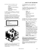
COMPONENTS - GAS 28 1 2 3 4 27 5 26 6 25 7 24 8 9 10 23 12 SOLUTION PRESSURE REGULATOR TEMPERATURE BALANCE ORIFICE CHEMICAL CHECK VALVE 14 22 WARM BALANCE ORIFICE ON/OFF VALVE 11 13 SOLUTION TEMPERATURE CONTROL VALVE HOT CONDENSED OPERATING INSTRUCTIONS STARTING SOLUTION SCREEN 21 20 1. CONNECT WATER HOSES TO WATER INLET CONNECTIONS AND TURN ON WATER SUPPLY. 2. CONNECT CLEANING AND VACUUM HOSES TO THE DESIRED CLEANING TOOL AND CONSOLE. 3.
COMPONENTS - GAS 1. WASTE TANK FULL INDICATOR LIGHT 8. This indicator light is activated when the waste tank is full. When lit the unit will shutdown protecting the equipment from damage. This also indicates that the waste tank must be emptied before the unit can be brought back in service. NOTE: Never dispose of waste water in storm drains, water ways or on ground areas. Always dispose of waste in accordance with local, state and federal laws.
COMPONENTS - GAS 22. WATER INLET 15. VACUUM INLETS The vacuum inlets serve as connecting point for vacuum hoses. This quick connect allows the water supply hose to be connected to the unit. 23. PRESSURE REGULATOR 16. SOLUTION OUTLETS The solution outlets are the connecting point for the high pressure cleaning hoses. These outlets are quick disconnects that allow hoses to be plugged into the unit.
COMPONENTS - GAS 27. FLOW SIMULATOR VALVE 29. TEMPERTURE BALANCE ORIFICE SHUTOFF VAVLE This valve allows solution to move through the machine and chemical to be injected simulating the cleaning process. This allows the operator to set the chemical flow level without connecting tools to the machine. It is also useful in troubleshooting. The valve is turned off by rotating the knob clockwise and opened by turning the knob counter clockwise. 28.
OPERATION - GAS WATER PUMPING AND HEAT TRANSFER SYSTEM The third stage of plumbing and heat exchange takes place in the 2nd heater core located in the heater box. This is the hottest point of the gases coming from the vac pump and the engine. These hot gases are forced through heater core #2 creating the third stage of heat transfer to the cleaning solution. Cold water enters the console through the water inlet. When the water box is full the valve will automatically shut off.
OPERATION - GAS SINGLE SYSTEM WATER FLOW DIAGRAM LOW PRESSURE = COLD WATER = WARM WATER WASTE TANK = HOT WATER VACUUM EXHAUST HEAT EXCHANGERS THERMO RELIEF WATER BOX HELI-COIL ENGINE COOLANT HEAT EXCHANGER ENGINE WATER PUMP ENGINE THERMOSTAT RADIATOR TO PRESSURE GUAGE 3-WAY BALL VALVE ACCUMULATOR MANIFOLD WATER INLET LOW PRESSURE REGULATOR WARM WATER OUTLET TEMPERATURE BALANCE ORIFICE VALVE OUTLET CHECK VALVE OUTLET Y-STRAINER CHEMICAL INJECTION SOLUTION OUTLETS SOLUTION OUTLET MANIFOLD APE
OPERATION - GAS CHEMICAL INJECTION SYSTEM The chemical injection system is unique in that it utilizes the pressure spikes generated by the highpressure water pump to move chemical into the main pressure stream. The high pressure spikes move the diaphragm in the chemical pulse pump forcing small amounts of liquid chemical to be moved in a single direction of flow with the aid of two check valves.
OPERATION - GAS VACUUM SYSTEM The engine turning an air pump generates vacuum. The air is channeled in one side of the vacuum pump, compressed and discharged on the opposite side, creating airflow. The movement of air is used to do the work necessary for the extraction process. A vacuum nozzle applied to the carpet surface removes moisture, dirt and spent chemicals. These elements are conveyed back to a separating tank utilizing hoses and the force of air.
OPERATION - GAS PRE-RUN INSPECTION HIGH PRESSURE HOSE NOTE: Operation of this unit is simple. However, only trained personnel should proceed. Before starting the unit, connect the pressure hose(s) to the outlet connection(s) at the front of the unit. Connect the cleaning tool(s) to the pressure hose(s). Operate this unit and equipment only in a wellventilated area. Exhaust fumes contain carbon monoxide which is an odorless and deadly poison that can cause severe injury or fatality.
OPERATION - GAS PRIMING THE CHEMICAL PUMP 1. Connect water hose to water inlet connection and turn on water supply. 2. Connect cleaning and vacuum hoses to the desired cleaning tool and console. NEVER dispose of waste in storm drains, water ways, or on ground areas. Always dispose of waste in accordance with Local, State, and Federal laws. 5. Push in engine choke after engine has started. Once you have completed steps 1 through 8, proceed with the cleaning operation.
OPERATION - GAS UPHOLSTERY CLEANING DE-FLOODING OPERATIONS Upholstery tool, part #86285260 – PRV NO. 78513 De-flooding operations involve removal of water from carpet and flooring. This differs from normal cleaning operations in that no water or solution is required. An automatic waste pump-out is highly recommended for all de-flooding operations due to the large amount of water removal often required. 1. Set temperature as desired and slow down the engine speed to minimize excess heat. 2.
OPERATION - GAS WINTERIZING YOUR UNIT 1. Shut off the water supply. Disconnect the water inlet hose from the front of your console. 2. Connect all high pressure hoses and tools that may have water in them. 3. Start the unit and turn water pump on. Open the tool valve until water pressure drops and water stops flowing. 4. Fill the water box with approximately two gallons of 100% glycol base anti-freeze. 5. Turn the solution pump override switch to the override position and start the unit.
OPERATION - GAS REMOVING ANTI-FREEZE FROM THE UNIT 1. Connect one end of the winterizing loop hose to the solution outlet connection. Place the other end of the loop hose, without the attachment, into an approved container. 7. Place the chemical prime hose into the approved container. Submerge the chemical inlet hose in water. Turn the chemical valve to the PRIME position until clear water comes through the prime hose, and then remove the prime hose from the container. 2. Start the unit.
MAINTENANCE - GAS SERVICE SCHEDULE Engine Engine Daily Daily Water Pump Solution Inlet Tube Strainer Vacuum Inlet Filter (In Waste Tank) Vacuum Hoses Automatic Waste Pump Chemical Filter Vacuum Pump Water Box Float Valve Water Pump Inlet Filter Battery Solution Outlet Y-Strainer Temperature Balance Orifice Daily Daily Daily Daily Daily Daily Weekly* Weekly Weekly* Weekly* Weekly* Weekly Check engine oil level.
MAINTENANCE - GAS SERVICE SCHEDULE Vacuum Exhaust Heat Exchanger Water Pump Pulley Set Screws & Hub Cap Screws, Water Pump Clutch Shaft Bolts Drive Pulley Drive Pulley Drive Belts Drive Belts Chemical Pump & Check Valves Heater Core Engine Check Valve (Solution Outlet) Vacuum Pump Engine Engine Engine Nitrogen Accumulator Waste Tank Filters/Strainers Engine Battery Engine 500 hrs 500 hrs Inspect cores and remove debris. Change oil** 500 hrs Check for proper torque valves.
MAINTENANCE - GAS HEAT EXCHANGER SYSTEM MAINTENANCE KEY CHECKPOINTS NOTE: Initiation of a planned preventative maintenance program will assure that your unit has optimum performance, a long operating life, and a minimal amount of "down" time. ENGINE COOLANT SYSTEM (RADIATOR) MAINTENANCE Your engine radiator coolant system is an important part of the power plant operation.
MAINTENANCE - GAS DO NOT service this unit while it is running. The high-speed mechanical parts as well as high temperature components may result in severe injury, severed limbs, or fatality. NOTE: Use the hour meter as a guide for coordinating the maintenance schedule. 4. Check the spark plugs every 200 hours. Clean if necessary. Replace the spark plugs every 1000 hours. NOTE: Never sandblast spark plugs. Spark plugs should be cleaned by scraping or wire brushing.
MAINTENANCE - GAS VACUUM PUMP Refer to the Vacuum Pump Operation and Service Manual for specific instructions. Lubrication: We recommend that you use AEON PD Synthetic Blower Lubricant in the gear end of the vacuum pump for all operating temperatures. AEON PD is formulated especially for positive displacement blower service to provide maximum blower protection at any temperature. One filling of AEON PD will last a minimum of 2 times longer than a premium mineral oil. NOTE: AEON PD (Part# 86189090 – PRV NO.
MAINTENANCE - GAS WATER PUMP VACUUM PUMP DRIVE BELTS Refer to the Water Pump Operation and Service Manual for specific instructions. To tighten the vacuum pump belts: 1. Check the crankcase oil level daily to assure the proper level. Use the illustration as a guide when checking the oil level. If the level has dropped, check for the source of leakage and repair. 2. Use the provided dipstick. Remove black cap with attached dipstick. Oil level should be between marks on the dipstick.
MAINTENANCE - GAS WATER PUMP DRIVE BELT Y-STRAINER (OUTLET) To tighten the water pump belt: 1. Loosen the nuts which hold the water pump mount to base. Inspect the Y-strainer after the first week of running the unit by unscrewing the screen and remove any accumulated debris. Inspect the strainer again at 2 and 4 weeks. 2. Adjust the position of the belt tension adjusting bolt until the proper belt tension is achieved. (1/2" deflection in the center of the belt, halfway between the pulleys).
MAINTENANCE - GAS NITROGEN ACCUMULATOR 3. Clean any debris from the strainer and orifice plate. The nitrogen accumulator is pressurized to 250 PSI and must be replaced periodically. The accumulator cannot be repaired or recharged. We recommend replacement every 1000 hours of use. 4. Reassemble as shown in Parts Section - Solution Outlet. ENGINE COOLANT REPLACEMENT PRESSURE REGULATOR For the procedure, see the "General Service Adjustments” section in this manual for details.
MAINTENANCE - GAS GENERAL SERVICE ADJUSTMENTS USE EXTREME CAUTION while servicing while machine is running. The high-speed mechanical parts as well as high temperature components may result in severe injury, severed limbs, or fatality.
MAINTENANCE - GAS CHECK VALVE (SOLUTION OUTLET) CHEMICAL PUMP Inspect the check valve whenever doing service on the chemical pump or if flow problems occur in the chemical system: The only repairs which the chemical pump may require is the replacement of the diaphragm or check valves. To replace the diaphragm, unscrew the cover from the body. When replacing the diaphragm, lubricate the outer edges of the diaphragm with o-ring lubricant Part # 86265430 – PRV NO. 05-008035 and reassemble.
MAINTENANCE - GAS PRESSURE REGULATORS PACKING NUT ADJUSTMENT FOR CHEMICAL METERING AND CHEMICAL SELECTOR VALVES Examine the packing nut on the chemical metering, flow simulator, and chemical selector valves for proper tension every 200 hours. When turning the knob, there should be a small amount of resistance. If not, slightly tighten the packing nut. DO NOT overtighten. Keeping the valve packings properly adjusted will eliminate possible leakage from the valve stems and add to overall valve life.
TROUBLESHOOTING - GAS PROBLEM CAUSE Water supply is turned off or the float valve is stuck or improperly adjusted. NOTE: This may also cause the water pressure switch to disengage pump. Water pump inlet supply line is plugged or drawing air. NOTE: This may also cause the water pressure disengage pump. Improper engine speed Loss of water pump pressure. With the cleaning tool open, the water pressure gauge reads below the normal operating pressure. Pressure regulator o-rings are dry.
TROUBLESHOOTING - GAS PROBLEM Loss of vacuum While cleaning, the vacuum is not up to specification. Engine RPM is normal. Loss of chemical With the cleaning tool valve open, no chemical Chemical flow meter indicates flow with the tool valve closed CAUSE SOLUTION Examine the tubing between the vacuum Vacuum gauge is giving an improper relief valve and the vacuum gauge and reading. remove any blockage. Vacuum hose(s) is damaged, Inspect hose(s), repair or replace. causing a suction leak.
TROUBLESHOOTING - GAS PROBLEM CAUSE Solution pump circuit breaker has been tripped Defective electrical connection in the console wiring or defective switch. Water pump does not engage Water pump has not been activated Turn solution pump switch to on. Defective water pump clutch. If there is power in the switch, but not power at the clutch, replace the defective wire. If there is power at the clutch, replace the defective switch. Loose or broken water pump belts. Tighten or replace belts.
TROUBLESHOOTING - GAS PROBLEM Starter turns over engine, but will not start Engine stops running While doing normal cleaning, the engine stops running CAUSE Engine is malfunctioning Engine is out of gasoline Waste tank is full Main or engine circuit breaker on the control panel has been tripped. Engine coolant temperture has exceeded 240°F, triggering the high temperature switch to shut the unit down. Defective fuel pump. Defective float switch inside the waste tank.
NOTES: 4-16 APEX 86037630
APEX DIESEL APEX 86037630
SAFETY - DIESEL IMPORTANT SAFETY INSTRUCTIONS When using this machine, basic precautions must always be followed, including the following: READ ALL INSTRUCTIONS BEFORE USING THIS MACHINE. These symbols mean WARNING or CAUTION. Failure to follow warnings and cautions could result in fatality, personal injury to yourself and/or others, or property damage. Follow these instructions carefully! Read the operator's manual before installing or starting this unit.
SAFETY - DIESEL DO NOT leave the vehicle engine running while operating this unit. Dangerous Acid, Explosive Gases! Batteries contain sulfuric acid. To prevent acid burns, avoid contact with skin, eyes and clothing. Batteries produce explosive hydrogen gas while being charged. To prevent a fire or explosion, charge batteries only in well ventilated areas. Keep sparks, open flames, and other sources of ignition away from the battery at all times. Keep batteries out of the reach of children.
HAZARD INTENSITY LEVEL - DIESEL The following WARNING LABELS are found on your cleaning unit . These labels point out important Warnings and Cautions which should be followed at all times. Failure to follow warnings and cautions could result in fatality, personal injury to yourself and/or others, or property damage. Follow these instructions carefully! DO NOT remove these labels. NOTE: If at any time the labels become illegible, promptly replace them.
OPERATION - DIESEL TECHNICAL SPECIFICATIONS – DIESEL ENGINES ITEM DIMENSION/CAPACITY Engine speed Water pump rpm Vacuum pump rpm Water flow rate Water pump pressure Vacuum relief valve Waste tank capacity Console weight Console weight (with waste tank & waste tank accessories) 2850 rpm (high speed) Water Pump ON 1300 rpm (idle speed) Water Pump OFF. 1000 rpm 2600 rpm 4.15 GPM (maximum) 1000 PSI (maximum) 13” Hg 80 gallons 910 lbs. 1160 lbs. (1830 lbs.
OPERATION - DIESEL INSTALLATION REQUIREMENTS DEALER RESPONSIBILITY FUEL REQUIREMENTS Use diesel fuel ONLY. NOTE: Your distributor from whom you purchased this mobile cleaning unit is responsible for the correct installation of this machine. The dealer is also responsible for initial training of your operators and maintenance personnel in the proper operation and maintenance of this unit. 1. The unit should NOT be mounted in any motor vehicle of less than 3/4 ton capacity.
OPERATION - DIESEL CHEMICAL REQUIREMENTS4. C This cleaning unit, due to its chemical injection pump design, can be used with a variety of water-diluted chemical compounds (either acidic or alkaline), depending on the job to be done. However, to obtain optimum results with this unit, we recommend using the PROCHEM line of chemicals. For information on using the cleaning compounds, refer to the PROCHEM chemical manual.
COMPONENTS - DIESEL 1 2 28 3 4 5 27 6 26 7 25 8 24 9 10 12 11 13 23 SOLUTION PRESSURE REGULATOR TEMPERATURE BALANCE ORIFICE 14 CHEMICAL CHECK VALVE 22 WARM BALANCE ORIFICE ON/OFF VALVE SOLUTION TEMPERATURE CONTROL VALVE HOT CONDENSED OPERATING INSTRUCTIONS STARTING SOLUTION SCREEN 21 20 1. CONNECT WATER HOSES TO WATER INLET CONNECTIONS AND TURN ON WATER SUPPLY. 2. CONNECT CLEANING AND VACUUM HOSES TO THE DESIRED CLEANING TOOL AND CONSOLE. 3.
COMPONENTS - DIESEL 1. WASTE TANK FULL INDICATOR LIGHT 8. SOLUTION PUMP SWITCH This indicator light is activated when the waste tank is full. When lit the unit will shutdown protecting the equipment from damage. This also indicates that the waste tank must be emptied before the unit can be brought back in service. NOTE: Never dispose of waste water in storm drains, water ways or on ground areas. Always dispose of waste in accordance with local, state and federal laws. 2.
COMPONENTS - DIESEL 21. WARM WATER OUTLET 14. OIL CUP The oil cup allows lubricant spray to reach the vacuum blower. The warm water outlet allows the cleaning technician to drain hot water from the water box for mixing chemical. 15. VACUUM INLETS The vacuum inlets serve as connecting point for vacuum hoses. Water from this valve is hot. 22. WATER INLET 16. SOLUTION OUTLETS The solution outlets are the connecting point for the high pressure cleaning hoses.
COMPONENTS - DIESEL 27. FLOW SIMULATOR VALVE This valve allows solution to move through the machine and chemical to be injected simulating the cleaning process. This allows the operator to set the chemical flow level without connecting tools to the machine. It is also useful in troubleshooting. The valve is turned off by rotating the knob clockwise and opened by turning the knob counter clockwise. 29.
OPERATION - DIESEL WATER PUMPING AND HEAT TRANSFER SYSTEM The third stage of plumbing and heat exchange takes place in the 2nd heater core located in the heater box. This is the hottest point of the gases coming from the vac pump and the engine. These hot gases are forced through heater core #2 creating the third stage of heat transfer to the cleaning solution. Cold water enters the console through the water inlet. When the water box is full the valve will automatically shut off.
OPERATION - DIESEL SINGLE SYSTEM WATER FLOW DIAGRAM LOW PRESSURE = COLD WATER = WARM WATER WASTE TANK = HOT WATER VACUUM EXHAUST HEAT EXCHANGERS THERMO RELIEF WATER BOX HELI-COIL ENGINE COOLANT HEAT EXCHANGER ENGINE WATER PUMP ENGINE THERMOSTAT RADIATOR TO PRESSURE GUAGE 3-WAY BALL VALVE ACCUMULATOR MANIFOLD WATER INLET LOW PRESSURE REGULATOR WARM WATER OUTLET TEMPERATURE BALANCE ORIFICE VALVE OUTLET CHECK VALVE OUTLET Y-STRAINER CHEMICAL INJECTION SOLUTION OUTLETS SOLUTION OUTLET MANIFOLD
OPERATION - DIESEL The chemical injection system is unique in that it utilizes the pressure spikes generated by the highpressure water pump to move chemical into the main pressure stream. The high pressure spikes move the diaphragm in the chemical pulse pump forcing small amounts of liquid chemical to be moved in a single direction of flow with the aid of two check valves.
OPERATION - DIESEL VACUUM SYSTEM The engine turning an air pump generates vacuum. The air is channeled in one side of the vacuum pump, compressed and discharged on the opposite side, creating airflow. The movement of air is used to do the work necessary for the extraction process. A vacuum nozzle applied to the carpet surface removes moisture, dirt and spent chemicals. These elements are conveyed back to a separating tank utilizing hoses and the force of air.
OPERATION - DIESEL PRE-RUN INSPECTION HIGH PRESSURE HOSE NOTE: Operation of this unit is simple. However, only trained personnel should proceed. Before starting the unit, connect the pressure hose(s) to the outlet connection(s) at the front of the unit. Connect the cleaning tool(s) to the pressure hose(s). Operate this unit and equipment only in a wellventilated area. Exhaust fumes contain carbon monoxide which is an odorless and deadly poison that can cause severe injury or fatality.
OPERATION - DIESEL PRIMING THE CHEMICAL PUMP 1. Connect water hose to water inlet connection and turn on water supply. 2. Connect cleaning and vacuum hoses to the desired cleaning tool and console. 3. Insert chemical inlet and prime tubing into chemical container. 4. Turn ignition switch counterclockwise until glow plug light goes off. Turn solution pump switch to override, and turn ignition key clockwise to start. NEVER dispose of waste in storm drains, water ways, or on ground areas.
OPERATION - DIESEL UPHOLSTERY CLEANING DE-FLOODING OPERATIONS Upholstery tool, part #86285260 – PRV NO.78513 De-flooding operations involve removal of water from carpet and flooring. This differs from normal cleaning operations in that no water or solution is required. An automatic waste pump-out is highly recommended for all de-flooding operations due to the large amount of water removal often required. 1. Set temperature as desired and slow down the engine speed to minimize excess heat. 2.
OPERATION - DIESEL WINTERIZING YOUR UNIT 1. Shut off the water supply. Disconnect the water inlet hose from the front of your console. 2. Connect all high pressure hoses and tools that may have water in them. 3. Start the unit and turn water pump on. Open the tool valve until water pressure drops and water stops flowing. 4. Fill the water box with approximately two gallons of 100% glycol base anti-freeze. 5. Turn the solution pump override switch to the override position and start the unit.
OPERATION - DIESEL REMOVING ANTI-FREEZE FROM THE UNIT 1. Connect one end of the winterizing loop hose to the solution outlet connection. Place the other end of the loop hose, without the attachment, into an approved container. 7. Place the chemical prime hose into the approved container. Submerge the chemical inlet hose in water. Turn the chemical valve to the PRIME position until clear water comes through the prime hose, and then remove the prime hose from the container. 2. Start the unit.
MAINTENANCE - DIESEL SERVICE SCHEDULE Engine Engine Vacuum Pump Water Pump Solution Inlet Tube Strainer Vacuum Inlet Filter (In Waste Tank) Vacuum Hoses Automatic Waste Pump Chemical Filter Vacuum Pump Water Box Float Valve Water Pump Inlet Filter Battery Solution Outlet Y-Strainer Temperature Balance Orifice Heater Cores High Pressure Hoses Pressure Regulators Engine Engine Battery Engine Float Valve Seal Engine Engine Fuel Pump Flow Simulator And Chemical Valves Daily Daily Daily Daily Daily Daily Daily
MAINTENANCE - DIESEL SERVICE SCHEDULE Water Pump Pulley Set Screws & Hub Cap Screws 500 hrs Drive Pulley Drive Pulley Drive Belts Drive Belts Chemical Pump & Check Valves Check Valve (Solution Outlet) Vacuum Pump Engine Engine Nitrogen Accumulator Waste Tank Filters/Strainers Engine Battery 500 hrs 500 hrs 500 hrs 500 hrs 500 hrs 1000 hrs 1500 hrs Yearly Yearly* Yearly* Yearly 2 years 2 years 500 hrs Change oil** Check for proper torque valves.
MAINTENANCE - DIESEL HEAT EXCHANGER SYSTEM MAINTENANCE KEY CHECKPOINTS NOTE: Initiation of a planned preventative maintenance program will assure that your unit has optimum performance, a long operating life, and a minimal amount of "down" time. ENGINE COOLANT SYSTEM (RADIATOR) MAINTENANCE Your engine radiator coolant system is an important part of the power plant operation.
MAINTENANCE - DIESEL DO NOT service this unit while it is running. The high-speed mechanical parts as well as high temperature components may result in severe injury, severed limbs, or fatality. NOTE: Use the hour meter as a guide for coordinating the maintenance schedule. ENGINE 1. Check the engine oil level daily, when in use. Make certain that proper oil level is maintained. NEVER overfill. 6. Check the coolant level in the radiator overflow container daily.
MAINTENANCE - DIESEL VACUUM PUMP Refer to the Vacuum Pump Operation and Service Manual for specific instructions. Lubrication: We recommend that you use AEON PD Synthetic Blower Lubricant in the vacuum pump for all operating temperatures. AEON PD is formulated especially for positive displacement blower service to provide maximum blower protection at any temperature. One filling of AEON PD will last a minimum of 3 times longer than a premium mineral oil. NOTE: AEON PD (Part #86189090 PRV NO.
MAINTENANCE - DIESEL WATER PUMP VACUUM PUMP DRIVE BELTS Refer to the Water Pump Operation and Service Manual for specific instructions. To tighten the vacuum pump belts: 1. Check the crankcase oil level daily to assure the proper level. Use the illustration as a guide when checking the oil level. If the level has dropped, check for the source of leakage and repair. 2. Use the dipstick or sightglass to check oil level daily. Oil level should be between marks on the dipstick or centered in sightglass.
MAINTENANCE - DIESEL WATER PUMP DRIVE BELT Y-STRAINER (OUTLET) To tighten the water pump belt: 1. Loosen the nuts which hold the water pump mount to base. Inspect the Y-strainer after the first week of running the unit by unscrewing the screen and remove any accumulated debris. Inspect the strainer again at 2 and 4 weeks. 2. Adjust the position of the belt tension adjusting bolt until the proper belt tension is achieved. (1/2" deflection in the center of the belt, halfway between the pulleys).
MAINTENANCE - DIESEL NITROGEN ACCUMULATOR 3. Clean any debris from the strainer and orifice plate. The nitrogen accumulator is pressurized to 250 PSI and must be replaced periodically. The accumulator cannot be repaired or recharged. We recommend replacement every 1000 hours of use. 4. Reassemble as shown in Parts Section - Solution Outlet. ENGINE COOLANT REPLACEMENT PRESSURE REGULATOR For the procedure, see the "General Service Adjustments” section in this manual for details.
MAINTENANCE - DIESEL GENERAL SERVICE ADJUSTMENTS USE EXTREME CAUTION while servicing while machine is running. The high-speed mechanical parts as well as high temperature components may result in severe injury, severed limbs, or fatality. ENGINE SPEED 1. This unit uses a governor to set and maintain engine speed. The engine speed is adjusted by pulling the throttle cable out to maximum travel for high speed operation.
MAINTENANCE - DIESEL CHECK VALVE (SOLUTION OUTLET) CHEMICAL PUMP Inspect the check valve whenever doing service on the chemical pump or if flow problems occur in the chemical system: The only repairs which the chemical pump may require is the replacement of the diaphragm or check valves. To replace the diaphragm, unscrew the cover from the body. When replacing the diaphragm, lubricate the outer edges of the diaphragm with o-ring lubricant Part #86265430 – PRV NO. 05-008035 and reassemble.
MAINTENANCE - DIESEL PRESSURE REGULATOR PACKING NUT ADJUSTMENT FOR CHEMICAL METERING AND CHEMICAL SELECTOR VALVES Examine the packing nut on the chemical metering, flow simulator, and chemical selector valves for proper tension every 200 hours. When turning the knob, there should be a small amount of resistance. If not, slightly tighten the packing nut. DO NOT overtighten. Keeping the valve packings properly adjusted will eliminate possible leakage from the valve stems and add to overall valve life.
TROUBLESHOOTING - DIESEL PROBLEM CAUSE Water supply is turned off or the float valve is stuck or improperly adjusted. Water pump inlet supply line is plugged or drawing air. Improper engine speed Loss of water pump pressure. With the cleaning tool open, the water pressure gauge reads below the normal operating pressure. Pressure regulator o-rings are dry. Pressure regulator has worn o-rings Pressure regulator is dirty, stuck open, or improperly adjusted. Low pump volume.
TROUBLESHOOTING - DIESEL PROBLEM Loss of vacuum While cleaning, the vacuum is not up to specification. Engine RPM is normal. Loss of chemical With the cleaning tool valve open, no chemical Chemical flow meter indicates flow with the tool valve closed CAUSE SOLUTION Examine the tubing between the vacuum Vacuum gauge is giving an improper relief valve and the vacuum gauge and reading. remove any blockage. Ensure vent hole is present in black plug.
TROUBLESHOOTING - DIESEL PROBLEM CAUSE Solution pump circuit breaker has been tripped Defective electrical connection in the console wiring or defective switch. Water pump does not engage Water pump has not been activated Turn solution pump switch to on. Defective water pump clutch. If there is power in the switch, but not power at the clutch, replace the defective wire. If there is power at the clutch, replace the defective switch. Loose or broken water pump belts. Tighten or replace belts.
TROUBLESHOOTING - DIESEL PROBLEM Starter turns over engine, but will not start Engine stops running while doing normal cleaning, the engine stops running CAUSE Engine is malfunctioning Engine is out of fuel Waste tank is full Main or engine circuit breaker on the control panel has been tripped. Engine coolant temperture has exceeded 240°F, triggering the high temperature switch to shut the unit down. Defective fuel pump. Defective float switch inside the waste tank.
NOTES: 7-16 APEX 86037630
PARTS APEX 86037630
FRAME 25 26 27 1 2 24 11 9 6 22 3 4 5 3 7 2 20 10 19 21 8 3 18 7 9 2 17 3 2 1 11 16 12 3 3 15 23 12 3 14 3 15 9 13 8-1 APEX 86037630
FRAME REF PART NO. PRV NO.
FRAME 2 1 3 4 5 9 10 6 12 7A 7B 13 8 11 8-3 APEX 86037630
FRAME REF PART NO. PRV NO. QTY 1 2 3 4 5 6 7A 7B 8 9 10 11 12 13 86030290 86193550 86189660 86193220 86191570 86055840 86179340 86179320 86277730 86005680 86270330 86275460 86233410 86005770 790970 00-000272 58-700023 02-000268 01-000259 790957 791103 790958 790465 57047 02-000066 70481 81270 57119 1 13 13 13 13 1 1 1 4 4 4 1 2 2 DESCRIPTION SERIAL NO.
SIDE PANEL, RIGHT TO VACUUM RELIEF VALVE 5 8 3 8-5 APEX 86037630
SIDE PANEL, RIGHT REF PART NO. PRV NO. QTY 1 2 3 4 5 6 7 8 86330040 86180370 86186470 86180700 86049000 86177220 86178700 86046030 12-800099 500694 32064 09-805380 03-000054 19-800075 790430 1 1 1 2 2 2 1 1 DESCRIPTION BRKT, VAC INLET, APEX ELL, 1/8P X 1/4 POLY BR LABEL, VAC/WTR INLET END CAP, VAC INLET, 1 1/2 HOSE, INT VAC 2.0 X 60.0 BLK CLMP, HOSE #32 1.5625/2.5 SST CUP, OIL FILL 1/8P BRKT, VAC INLET SERIAL NO. FROM ** NOTES: *(1) *SEE SERIAL NUMBER PAGE. **CALL MANUFACTURER FOR SERIAL NUMBER.
SIDE PANEL, LEFT TO WATER BOX FILL TO WATER BOX (SIDE) 12 1 2 3 14 4 7 13 11 8 5 6 9 8-7 APEX 86037630
SIDE PANEL, LEFT REF PART NO. PRV NO. QTY 1 2 3 4 5 6 7 8 9 10 11 12 13 14 86046040 86173640 86188080 86179710 86195230 86195180 86186470 86188180 86173530 86177050 86177220 86181400 86048880 86181360 790431 11-800437 11-800102 13-806008 15-808008 84196 500694 11-800300 790506 03-000176 03-000054 12-800345 09-805090 12-800269 1 1 1 1 1 1 1 1 1 2 1 1 1 1 DESCRIPTION SERIAL NO.
CHEMICAL CONTROL PANEL 1 2 1 14 13 4 3 1 2 15 10 5 9 7 8 7 6 11 12 8-9 APEX 86037630
CHEMICAL CONTROL PANEL REF PART NO. PRV NO. QTY 1 2 3 4 5 6 7 8 9 10 11 12 13 14 15 86177660 86195050 86180360 86055700 86186890 86181170 86181300 86180140 86297070 86247720 86274290 86279470 86189050 86273180 86270330 12-800065 15-808106 12-800040 790910 500692 18-808513 12-800093 11-800014 56032 70162 87165 790464 00-000078 02-000066 3 2 1 1 1 1 3 1 1 1 2 2 2 2 2 DESCRIPTION SERIAL NO.
CONTROL PANEL - GAS 1 28 24 30 29 5 25 6 4 27 2 7 3 10 9 26 9 8 33 11 16 15 21 12 20 19 13 14 17 8 18 7 22 8-11 23 APEX 86037630
CONTROL PANEL - GAS REF PART NO. PRV NO.
CONTROL PANEL - DIESEL 8-13 APEX 86037630
CONTROL PANEL - DIESEL REF PART NO. PRV NO.
ENGINE - GAS 27 37 1 5 43 36 3 2 6 44 40 38 39 8 35 36 28 4 7 30 31 29 41 22 21 23 32 17 18 33 16 24 26 42 15 19 3 13 11 10 20 9 TO FRAME 8-15 25 12 34 APEX 86037630 14
ENGINE - GAS REF PART NO. PRV NO.
ENGINE - GAS BRKT, LEFT ENG MTG (REFERENCE) 4 11 14 12 11 10 16 11 3 14 14 12 11 12 2 1 13 18 6 17 8 7 3 15 9 8 11 11 5 7 8-17 APEX 86037630
ENGINE - GAS REF PART NO. PRV NO. QTY 1 2 3 4 5 6 7 8 9 10 11 12 13 14 15 16 17 18 86181620 86176990 86005680 86173910 86273330 86046170 86179920 86179930 86005770 86185600 86270330 86274750 86265730 86010780 86279510 86046210 86177390 86323830 14-806574 03-000065 57047 790780 00-000286 790961 790605 790606 57119 790986 02-000066 70270 04-000053 87162 87171 791131 791166 - 1 6 2 1 1 1 2 2 4 1 11 8 3 8 4 1 1 1 DESCRIPTION SERIAL NO.
ENGINE - DIESEL 27 13 28 34 1 3 44 2 3 6 17 19 35 5 15 28 20 INCLUDED WITH ENGINE 3 32 7 33 4 8 30 31 29 38 18 22 21 37 40 18 39 23 2 26 19 24 12 16 45 41 36 42 9 10 TO FRAME 8-19 2 11 43 APEX 86037630 25 14
ENGINE - DIESEL REF PART NO.
ENGINE - DIESEL BRKT, LEFT ENG MTG (REFERENCE) 11 4 3 2 12 4 7 4 2 3 13 5 9 8 12 1 6 4 4 10 8-21 APEX 86037630
ENGINE - DIESEL REF PART NO. PRV NO. QTY 1 2 3 4 5 6 7 8 9 10 11 12 13 86279510 86010780 89274750 86270330 86185080 86005770 86046210 86179920 86046170 86273330 86173910 86005680 86176990 87171 87162 70270 02-000066 791114 57119 791131 790605 790961 00-000286 790780 57047 03-000065 4 7 4 8 1 4 1 1 1 1 1 3 4 DESCRIPTION SERIAL NO.
COOLANT SYSTEM 13 12 10 14 15 10 11 16 TO ENGINE 3 1 10 9 5 4 3 2 8 7 6 8-23 APEX 86037630
COOLANT SYSTEM REF PART NO. PRV NO. QTY 1 2 3 4 5 6 7 8 9 10 11 12 13 14 15 16 86191530 86055820 86270330 86010780 86274750 86278380 86010730 86195590 86189050 86177020 86177310 86176990 86175820 86273260 86173590 86273180 790918 790953 02-000066 87162 70270 70825 87088 790930 790464 03-000113 03-000248 03-000065 140642 00-000216 790936 00-000078 1 1 6 4 4 2 2 4 2 4 3 2 1 2 1 2 DESCRIPTION SERIAL NO.
VACUUM BLOWER 7 4 3 2 5 1 15A 15B 10A 10B 23 24 11 12 13 13 18 16 19 21 2 22 2 2 20 14 2 18 17 8-25 APEX 86037630
VACUUM BLOWER REF PART NO. PRV NO.
WATER PUMP 34 35 1 3 4 2 5 TO WATER BOX TO TOP OF FLOWMETER 18 20 21 19 6 16 7 17 8 9 31 15 10 14 32 29 24 25 22 28 27 33 13 30 11 12 25 24 23 26 8-27 APEX 86037630
WATER PUMP REF PART NO. PRV NO.
WATER PUMP 4 11 5 6 1 2 7 8 9 3 8-29 APEX 86037630
WATER PUMP REF PART NO. PRV NO.
VAC/EXHAUST HEAT EXCHANGER/SILENCER 35 34 33 31 26 36 2 4 5 7 7 6 20 14 22 29 21 7 13 12 6 4 5 1 23 28 12 24 6 29 5 9 32 15 1 4 7 8 7 3 19 6 5 1 18 15 9 8 10 25 11 10 30 8 8-31 APEX 86037630
VAC/EXHAUST HEAT EXCHANGER/SILENCER REF PART NO. PRV NO.
SOLUTION TEMPERATURE CONTOL VALVE 7 1 4 6 5 3 4 2 8-33 APEX 86037630
SOLUTION TEMPERATURE CONTROL VALVE REF PART NO. PRV NO. QTY DESCRIPTION 1 86177700 12-800282 1 CONN, 3/8P X 1/2T BR 2 86195540 84192 1 VLV, BALL, 3-WAY, HI-TEMP/PRES 3 4 5 6 7 86183230 86180410 86270330 86010780 86273800 38317 12-800225 02-000066 87162 70017 1 2 2 2 2 HNDL, VALVE, 3-WAY, HI P/T ELL, 3/8P X 1/2T BR FLATWASHER, 1/4 WASHER, 1/4 SPLIT LOCK SCR, CAP 1/4-20 X 2.50 HHCS APEX 86037630 SERIAL NO.
HELI-COIL HEAT EXCHANGER 10 13 12 11 1 14 10 9 2 3 4 5 7 6 4 9 6 TO TEE FITTING 8 TO PRESSURE REGULATOR 8-35 APEX 86037630
HELI-COIL HEAT EXCHANGER REF PART NO. PRV NO. QTY 1 2 3 4 5 6 7 8 9 10 11 12 13 14 86177560 86197360 86177310 86181420 86180260 86180430 86180000 86005770 86279510 86275860 86046060 86233410 86191570 86048290 15-808073 31016 03-000248 12-800361 11-800401 12-800326 31093 57119 87171 70554 790445 81270 01-000259 57-520073 1 1 2 2 1 2 1 2 2 2 1 1 1 1 DESCRIPTION SERIAL NO.
SOLUTION OUTLET 2 1 3 4 7 5 6 21 20 16 24 23 22 25 26 27 28 9 17 30 29 8 10 11 15 8 14 18 19 13 12 8-37 APEX 86037630
SOLUTION OUTLET REF PART NO. PRV NO.
WATER BOX 12 6 7 1 2 3 8 9 13 14 9 24 REAR 4 5 25 11 28 27 32 2 31 26 3 33 15 16 FROM WATER INLET 29 30 18 13 19 FRONT 14 20 21 8-39 APEX 86037630 33 17
WATER BOX REF PART NO. 1 2 3 4 5 6 7 8 9 10 11 12 13 14 15 16 17 18 19 20 21 22 23 24 25 26 27 28 29 30 31 32 33 86180170 86181360 86177060 86180250 86195060 86187460 86057160 86005680 86270330 86194120 86273330 86176400 86193440 86188180 86270770 86056660 86348200 86175870 86190480 86181370 86177020 86177660 86175860 86195340 86180420 86024750 86189010 86309160 86308950 86309140 86189870 86192380 86010660 PRV NO.
PRESSURE REGULATOR FROM LOWER ELBOW ON HELICOIL ASSEMBLY 17 13 9 10 1 7 12 2 11 8 14 15 16 7 3 4 6 5 8-41 APEX 86037630
PRESSURE REGULATOR REF PART NO. PRV NO. QTY DESCRIPTION 1 86180450 12-800347 1 2 86191660 790067 1 3 4 5 6 7 8 9 10 11 12 13 14 15 16 17 86177060 86181400 86180210 86177700 86190520 86188390 86175920 86190480 86187770 86180570 86173460 86270330 86010780 86273330 86180360 03-000246 12-800345 11-800275 12-800282 11-800224 11-800429 11-800118 11-800069 790901 31098 790106 02-000066 87162 00-000286 12-800040 1 1 1 1 1 1 1 1 1 1 1 2 2 2 1 SERIAL NO.
AFTER SERIAL NUMBER ** WASTE TANK – 100 GALLON 3 12 16 2 11 14 8 7 10 13 1 9 12 15 18 19 17 5 6 4 8-43 APEX 86037630
AFTER SERIAL NUMBER ** WASTE TANK – 100 GALLON REF PART NO. PRV NO. QTY DESCRIPTION 1 2 3 4 5 6 7 8 9 10 11 12 13 14 15 16 17 18 19 86328460 86325770 86325720 86325650 86323700 86323580 86318560 86202240 86193870 86010630 86273810 86273020 86005810 86043190 86186860 86193540 86180340 86190530 86272720 791066 87013 70018 67006 57245 56-501793 46-802510 14-806569 12-800031 11-800402 11-800345 1 1 1 1 1 1 1 8 1 8 8 8 8 1 2 1 2 2 1 SERIAL NO.
BEFORE SERIAL NUMBER ** WASTE TANK – 80 GALLON 10 1 4A 4B 11 13 2 19 9 20 21 3 22 5A 5B 8 12 6 16 18 15 18 17 14 7 8-45 APEX 86037630
BEFORE SERIAL NUMBER ** WASTE TANK – 80 GALLON REF PART NO. PRV NO.
HOSE ACCESSORIES 1 23 2 3 22 2 7 4 5 10 6 11 12 9 8 17 14 13 18 19 15 21 20 16 8-47 APEX 86037630
HOSE ACCESSORIES REF PART NO. PRV NO.
BATTERY-FLOOR MOUNT 2 1 10 3 4 5 9 6 7 8 8-49 APEX 86037630
BATTERY-FLOOR MOUNT REF PART NO. PRV NO. QTY 1 2 3 4 5 6 7 8 9 10 86273780 86005680 86174580 86012060 86273190 86270330 86010780 86270770 86309890 86011470 70015 57047 36-900056 00-000132 02-000066 87162 57006 - 2 2 1 1 4 8 8 8 1 4 DESCRIPTION SERIAL NO.
EXHAUST - OPTIONAL 1 4 3 2 8-51 APEX 86037630
EXHAUST - OPTIONAL REF 1 2 3 4 5 - PART NO. 86177010 86280600 86181110 86192060 86005810 86030440 PRV NO. QTY DESCRIPTION 03-000112 2 CLAMP, #48 HOSE 09-805487 1 HOSE, 3" X 17" FLEXABLE 56-502131 1 FLANGE, VAC EXH DUCT KIT LG 00-000376 4 SCREW, 1/4-20 X 1-1/4" SST 57245 4 NUT, 1/4-20 HEX NYLOCK SS 47447 1 KIT, EXHAUST 3” ID, SINGLE APEX 86037630 SERIAL NO.
AUTOMATIC PUMPOUT - DUAL DIAPHRAGM - OPTIONAL 3 15 18 19 20 23 22 13 11 21 1 12 TO PUMPOUT TO ENGINE HARNESS 14 16 7 5 2 10 6 17 4 TO WASTE TANK 8-53 8 APEX 86037630
AUTOMATIC PUMPOUT - DUAL DIAPHRAGM - OPTIONAL REF PART NO. PRV NO.
AUTOMATIC PUMPOUT - OPTIONAL 11 17 19 16 6 10 7 18 10 1 4 5 5 3 7 2 5 13 6 5 14 4 3 8 8-55 9,12,15 APEX 86037630
AUTOMATIC PUMPOUT - OPTIONAL REF PART NO. PRV NO. QTY 1 2 3 4 5 6 7 8 9 10 11 12 13 14 15 16 17 18 19 86274150 86273190 86270770 86010780 86270330 86177050 86280680 86184780 86176420 86181430 86181440 86195820 86175720 86188970 86162270 86191380 86174260 86195860 86195910 70105 00-000132 57006 87162 02-000066 03-000176 09-805591 10-805484 12-800052 12-800367 12-800444 43-807008 50-502055 52-000123 52-501993 61-951306 61-951319 23719 72185 4 2 4 4 4 4 1 1 1 1 1 1 1 1 1 1 1 1 1 DESCRIPTION SERIAL NO.
AUTOMATIC PUMPOUT - OPTIONAL 26 36 23 15 1 24 16 37 19 22 11 22 11 17 27 26 3 29 30 32 25 20 9 34 31 33 18 5 14 13 28 4 8 7 35 6 21 39 10 8 21 38 21 10 12 2 21 5 8-57 APEX 86037630
AUTOMATIC PUMPOUT - OPTIONAL REF 1 2 3 4 5 6 7 8 9 10 11 12 13 14 15 16 17 PART NO. 86273250 86178820 86192020 86273550 86273280 86005810 86010780 86279470 86024840 86174520 86024850 86193250 86174700 86179530 86187870 86182540 86182550 18 19 20 21 22 23 24 25 26 27 28 29 30 31 32 33 34 35 36 37 PRV NO.
WAND-TITANIUM SIX JET-OPTIONAL 35 8 10 17 21 3 3 22 17 17 23 19 13 20 5 2 4 1 18 24 16 7 9 6A 6B 6C 14 15 11 12 31 29 28 25 32 26 30 27 33 8-59 APEX 86037630 34 8
WAND-TITANIUM SIX JET-OPTIONAL REF PART NO. 1 2 3 4 5 6A 6B 6C 7 8 9 10 11 12 13 14 15 16 17 18 19 20 21 22 23 24 25 26 27 28 29 30 31 32 33 34 35 PRV NO.
WAND-ERGONOMIC SIX JET-OPTIONAL 17 26 2A 2B 14 16 3 15 12 11 13 6 8 1 4 7 18 5 9 27 10 21 23 22 23 21 20 APEX 86037630 21 25 25 8-61 24 19 20
WAND – ERGONOMIC SIX JET - OPTIONAL REF PART NO. 1 2A 2B 3 4 5 6 7 8 9 10 11 12 13 14 15 16 17 18 19 20 21 22 23 24 25 26 27 - 86326900 86195560 86182820 86011740 86188590 86175760 86277760 86188280 86177870 86193490 86177860 86005580 86195600 86195610 86179020 86177650 86031580 86183110 86182120 86177150 86194450 86270990 86194580 86187620 86177710 86187610 86190180 86175660 86341590 86186100 PRV NO.
WAND-QUAD-JET-OPTIONAL 27 28 29 30 31 32 33 26 14 9, 10 34 16 17 8 7 12 11 4 6 5 2 13 15 3 14 1 21, 22 25 26 19, 20 23, 23A, 23B 19, 24 8-63 APEX 86037630
WAND-QUAD-JET-OPTIONAL REF PART NO. PRV NO.
WAND-TRI-JET-OPTIONAL 25 26 27 29 30 28 31 16 14 17 9, 10 14 32 8 7 12 6 5 4 11 13 15 3 2 1 24 23 20, 21, 22 8-65 APEX 86037630 19, 19A, 19B
WAND-TRI-JET-OPTIONAL SERIAL NO. FROM REF PART NO. PRV NO.
STAIR TOOL-OPTIONAL 16 17 18 20 19 21 22 2 3 23 4 6 5, 5A 7 8 9, 10 11 12 14 13 15, 15A 8-67 APEX 86037630
STAIR TOOL-OPTIONAL SERIAL NO. FROM REF PART NO. PRV NO.
UPHOLSTERY TOOL-OPTIONAL 20 21 22 23 27 24 25 28 26 29 30 37 31 8 34 36 33 32 7 6 35 4 11 3 5 1 9 10 12 14 16 2 13 18 15 19 17 3 8-69 APEX 86037630
UPHOLSTRY TOOL-OPTIONAL REF PART NO. PRV NO.
SHELF ASSEMBLY-OPTIONAL 16 4 3 17 2 1 4 3 2 4 15 3 2 6 2 3 5 4 7 10 8 2 5 9 12 2 11 10 14 4 13 10 2 5 OVERALL DIMENSION: 41-1/2" TALL 50-1/8" WIDE 57" WIDE (WITH TOOL HOLDERS) 7-7/8" DEEP 10 2 12 DIMENSIONAL DATA 50 1/8 7 5 1 8-71 3 4 2 APEX 86037630 11
SHELF ASSEMBLY-OPTIONAL REF 1 2 3 4 5 6 7 8 9 10 11 12 13 14 15 16 17 - PART NO. 86285410 86192680 86270330 86010780 86274760 86274750 86175710 86175730 86198090 86285120 86270620 86024890 86278840 86021920 86186850 86183180 86183170 86179350 PRV NO.
WATER TANK, DUAL WITH DEMAND PUMP-OPTIONAL 1 1 4 3 2 2 3 4 13 5 12 13 6 7 9 9 8 11 6 7 7 10 7 8 TO DEMAND PUMP 8 OVERALL DIMENSION: 32-1/2" TALL 62-5/8" WIDE 15-1/2" DEEP 14 8-73 APEX 86037630
WATER TANK, DUAL WITH DEMAND PUMP-OPTIONAL REF PART NO. PRV NO.
WATER TANK- DEMAND PUMP-OPTIONAL 3 2 4 1 11 6 5 4 10 4 9 12 13 16 16 8 7 8-75 APEX 86037630 8
WATER TANK- DEMAND PUMP-OPTIONAL REF PART NO. PRV NO.
AUXILIARY WATER TANK WITH PUMP 12 21 33 28 24 9 29 15 32 22 39 2 40 23 1 11 37 8 27 17 38 18 20 40 10 13 25 40 5 31 16 19 3 6 4 26 30 35 36 7 34 4 14 2X 18.7 4X Ø.406 MOUNTING DETAIL 2X 16.8 30.0 WIDE Vehicle Floor 34 58.6 LENGTH 30.
AUXILIARY WATER TANK WITH PUMP REF PART NO. PRV NO.
HOSE REEL - OPTIONAL OVERALL MOUNTING DETAIL 1 47" TALL 44-1/2" DEEP Vehicle Floor 21 23 22 24 25 17 13 14 15 5 6 16 8 13 14 2 7 12 15 16 15 3 9 2 5 3 13 6 10 11 12 10 14 7 9 4 8-79 APEX 86037630 8
HOSE REEL-OPTIONAL REF PART NO. PRV NO.
86193410 PRV NO. 14-806506 86181300 PRV NO. 12-800093 PRV NO. 03-000065 86176990 (2) CHEMICAL BOTTLE WASTE TANK WASTE TANK 86280260 (36") 86280350 (53") 86280390 ( 26-1/2) PRV NO. 09-805347 86183470 (23") PRV NO. 10-805204 86183440 (29") PRV NO. 10-805142 86183400 (33-1/2") PRV NO. 10-805107 CHEMICAL PANEL PRV NO. 09-805234 LEFT SIDE CONTROL PANEL VAC BLOWER 86280210 (17") PRV NO. 09-805071 86184370 (11-1/2") PRV NO. 790416 PRESSURE REGULATOR 86282380 (23") 86183400 (33-1/2") PRV NO.
86193410 PRV NO. 14-806506 86181300 PRV NO. 12-800093 86176990 (2) PRV NO. 03-000065 CHEMICAL BOTTLE WASTE TANK WASTE TANK 86280260 (36") 86280350 (53") 86280390 ( 26-1/2) PRV NO. 09-805347 PRV NO. 09-805234 LEFT SIDE CONTROL PANEL VAC BLOWER 86183470 (23") PRV NO. 10-805204 86183440 (29") PRV NO. 10-805142 86183400 (33-1/2") PRV NO. 10-805107 PRV NO. 09-805330 86176990 PRV NO. 03-000065 86280040 (64") PRV NO. 09-805088 86280040 (64") PRV NO. 09-805088 PRV NO.
TEMPERATURE SENDER #86192490 - PRV NO.
WIRING DIAGRAM - DIESEL APEX 86037630 8-84
SERIAL NUMBERS REF. NO. 1 2 3 4 5 6 8-85 MODEL: SERIAL #: 1.001-069.0, 1.001-072.0: 1000158501 1.001-069.0, 1.001-072.0: 1000165558 1.001-069.0, 1.001-072.0: 1000151479 1.001-069.0, 1.001-072.0: 10010770000119 1.001-069.0, 1.001-072.0: 1000161005 1.001-069.0, 1.001-072.