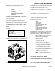
Operating Instructions (ENG) MODELS: EVEREST EFI LP EVEREST EFI HP Read instructions before operating the machine.
MODEL _______________________________________ DATE OF PURCHASE __________________________ SERIAL NUMBER ______________________________ SALES REPRESENTATIVE # _____________________ YOUR DEALER NAME: _________________________________________________________________________________________________ ADDRESS: _______________________________________________________________________________________________ PHONE NUMBER: _________________________________________________________________________________________ Wel
TABLE OF CONTENTS Machine Data Log/Overview.........................1 Table of Contents .........................................2 Receiving Your Unit ......................................4 HOW TO USE THIS MANUAL How to use this Manual. ...............................1-1 SAFETY Safety Instructions ....................................... 2-1 Hazard Intensity Level ..................................2-3 OPERATION & SYSTEMS Technical Specifications. ..............................
TABLE OF CONTENTS PARTS LIST Framework .................................................. 5-1 Side Panel, Right ........................................ 5-5 Side Panel, Left........................................... 5-7 Chemical Panel........................................... 5-9 Control Panel .............................................. 5-11 Engine......................................................... 5-13 Engine Coolant ........................................... 5-19 Vacuum Blower.................
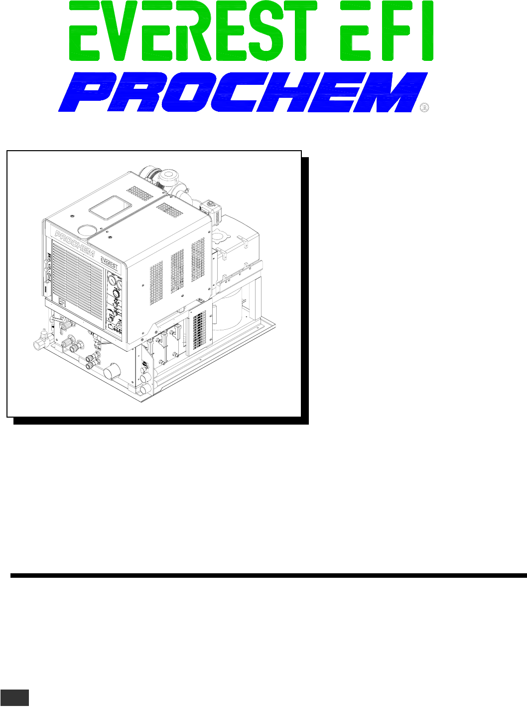
RECEIVING YOUR UNIT ACCEPTANCE OF SHIPMENT EQUIPMENT LIST: Every part of your cleaning unit was carefully checked, tested, and inspected before it left our manufacturing plant. Upon receiving the unit, make the following acceptance check: 1. Console. 2. Waste tank 3. Hose clamps for vacuum hoses. 1. The unit should not show any outward signs of damage. If damaged, notify the delivering carrier immediately. 4. 150 ft. of 2” vacuum hose. 5. 2 vacuum hose connectors. 2.
HOW TO USE THIS MANUAL This manual contains the following sections: - - HOW TO USE THIS MANUAL SAFETY INSTALLATION REQUIREMENTS SYSTEMS OPERATIONS MAINTENANCE & SERVICE PARTS LIST The HOW TO USE THIS MANUAL section will tell you how to find important information for ordering correct repair parts. Parts may be ordered from authorized dealers. When placing an order for parts, the machine model and machine serial number are important.
IMPORTANT SAFETY INSTRUCTIONS When using this machine, basic precautions must always be followed, including the following: READ ALL INSTRUCTIONS BEFORE USING THIS MACHINE. These symbols mean WARNING or CAUTION. Failure to follow warnings and cautions could result in fatality, personal injury to yourself and/or others, or property damage. Follow these instructions carefully! Read the operator's manual before installing or starting this unit.
DO NOT leave the vehicle engine running while operating this unit. Dangerous Acid, Explosive Gases! Batteries contain sulfuric acid. To prevent acid burns, avoid contact with skin, eyes and clothing. Batteries produce explosive hydrogen gas while being charged. To prevent a fire or explosion, charge batteries only in well ventilated areas. Keep sparks, open flames, and other sources of ignition away from the battery at all times. Keep batteries out of the reach of children.
HAZARD INTENSITY LEVEL The following WARNING LABELS are found on your cleaning unit . These labels point out important Warnings and Cautions which should be followed at all times. Failure to follow warnings and cautions could result in fatality, personal injury to yourself and/or others, or property damage. Follow these instructions carefully! DO NOT remove these labels. NOTE: If at any time the labels become illegible, promptly replace them.
OPERATIONS TECHNICAL SPECIFICATIONS ITEM DIMENSION/CAPACITY Engine speed Water pump rpm Vacuum pump rpm Water flow rate Water pump pressure (low pressure) Water pump pressure (high pressure) Vacuum relief valve Waste tank capacity Console weight Console weight (with waste tank & waste tank accessories) TORQUE VALUES Engine hub Vacuum pump hub Water pump shaft bolt 2200 rpm (medium speed) Water Pump ON 900 rpm (idle speed) Water Pump OFF. 1455 rpm 3400 rpm 4.
OPERATIONS INSTALLATION REQUIREMENTS DEALER RESPONSIBILITY NOTE: Your distributor from whom you purchased this mobile cleaning unit is responsible for the correct installation of this machine. The dealer is also responsible for initial training of your operators and maintenance personnel in the proper operation and maintenance of this unit. 1. The unit should NOT be mounted in any motor vehicle of less than 3/4 ton capacity.
OPERATIONS ELECTRONIC FUEL INJECTION SYSTEM EMISSION CONTROL INFORMATION This unit is equipped with the latest Zenith electronic fuel injection (EFI) technology. The EFI technology provides more effective fuel distribution and improved power management through the use of an electronic “brain” called the electronic control unit (ECU). The ECU also provides improved engine emissions through more effective combustion of the fuel/air mixture.
OPERATIONS DATE STAMP LOCATION FUEL PUMP AND FILTER When referring to an engine for assistance from your dealer, ProChem, or ZPP please identify your engine by the serial # and date code stamped on the machined surface next to the oil dipstick. Your Everest EFI console was shipped to the dealer with a specific fuel pump and fuel filter. Ensure that ONLY these items are used in the installation of your unit. The EFI system is much more sensitive to unwanted material in the fuel stream.
OPERATIONS ERROR CODES On rare occasions the engine may experience abnormal operation conditions and shut down. Upon shutdown the amber light in the upper right corner of the instrument panel will repeatedly flash an error code to help you determine the root cause of the shutdown. Double-digit numbers are flashed one digit at a time, (i.e. “12” would be shown as “Flash”, pause, “Flash”, “Flash”). The codes are listed below for your convenience.
OPERATIONS ZENITH DISTRIBUTOR LOCATIONS • ITAL ENGINE COMPANY (09046) 97 CYPRESS ST. SW REYNOLDSBURG, OHIO 43068 • CULLUM & BROWN, INC. (09045) 1607 WABASH WICHITA, KS 67214 • DIESEL ELECTRIC SERVICE & SUPPLY (09116) 652 W. 1700 SOUTH SALT LAKE CITY, UT 84104 UT • POWER EQUIPMENT COMPANY (09117) 15225 INDUSTRIAL RD. OMAHA, NE 68144 NE, IA PHONE:402/330-5100 • ENGINE WORKS, INC. (09178) 1345 PARAMOUNT PKWY. BATAVIA, IL 60510 • FRONTIER EQUIPMENT, LTD.
OPERATION & SYSTEMS CHEMICAL REQUIREMENTS4. C This cleaning unit, due to its chemical injection pump design, can be used with a variety of water-diluted chemical compounds (either acidic or alkaline), depending on the job to be done. However, to obtain optimum results with this unit, we recommend using the PROCHEM line of chemicals. For information on using the cleaning compounds, refer to the PROCHEM chemical manual.
OPERATION & SYSTEMS 1 2 30 3 4 5 6 29 8 28 7 27 9 26 10 25 11 24 SOLUTION PRESSURE 23 12 LOW PRESSURE SOLUTION REGULATOR HIGH PRESSURE 1000-3000 PSI WARM SOLUTION TEMPERATURE CONTROL VALVE HOT 13 CONDENSED OPERATING INSTRUCTIONS STARTING LOW PRESSURE SOLUTION SCREEN HIGH PRESSURE SOLUTION REGULATOR HIGH PRESSURE SOLUTION OUTLET 22 21 3-8 19 SHUTDOWN AND DAILY MAINTENANCE 1. CLOSE CHEMICAL METERING VALVE. 2.
COMPONENTS 1. WASTE TANK FULL INDICATOR LIGHT This indicator light is activated when the waste tank is full. When lit the unit will shutdown protecting the equipment from damage. This also indicates that the waste tank must be emptied before the unit can be brought back in service. NOTE: Never dispose of waste water in storm drains, water ways or on ground areas. Always dispose of waste in accordance with local state and federal laws. 2.
COMPONENTS 14. VACUUM INLETS 20. WASTE OUTLET The vacuum inlets serve as connecting point for vacuum hoses. This valve allows the waste tank to be emptied. Turning clockwise opens the valve. 15. SOLUTION OUTLETS The solution outlets are the connecting point for the high pressure cleaning hoses. These outlets are quick disconnects that allow hoses to be plugged into the unit. 16. SOLUTION SCREEN The solution screen is located on the front of the machine.
OPERATIONS & SYSTEMS 26. FLOW METER 29. FLOW SIMULATOR VALVE The flow meter is a gauge to indicate how much liquid chemical is being introduced in the water system. The quantity can be increased by turning the chemical flow knob counter clockwise. 27. CHEMICAL PRIME CONTROL VALVE This valve allows the chemical to circulate through the chemical system with little or no restriction. It also purges out air that may be trapped in the lines and cavities of the chemical pump.
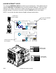
OPERATION & SYSTEMS WATER PUMPING AND HEAT TRANSFER SYSTEM Cold water enters the console through the water inlet. When the water box is full the valve will automatically shut off. Water then flows from the water box, through a strainer, into the water pump where it is pumped to the pressure regulator manifold where the pressure regulator provides and maintains the desired pressure setting.
OPERATIONS SINGLE SYSTEM WATER FLOW DIAGRAM LOW PRESSURE (WARM) EVEREST EFI 980197 06/30/04 3-13
OPERATIONS SINGLE SYSTEM WATER FLOW DIAGRAM LOW PRESSURE (HOT) 3-14 EVEREST EFI 980197 06/30/04
OPERATIONS The chemical injection system is unique in that it utilizes the pressure spikes generated by the highpressure water pump to move chemical into the main pressure stream. The high pressure spikes move the diaphragm in the chemical pulse pump forcing small amounts of liquid chemical to be moved in a single direction of flow with the aid of two check valves.
OPERATIONS VACUUM SYSTEM The engine turning an air pump generates vacuum. The air is channeled in one side of the vacuum pump, compressed and discharged on the opposite side, creating airflow. The movement of air is used to do the work necessary for the extraction process. A vacuum nozzle applied to the carpet surface removes moisture, dirt and spent chemicals. These elements are conveyed back to a separating tank utilizing hoses and the force of air.
OPERATIONS PRE-RUN INSPECTION PRESSURE HOSE NOTE: Operation of this unit is simple. However, only trained personnel should proceed. Before starting the unit, connect the pressure hose(s) to the outlet connection(s) at the front of the unit. Connect the cleaning tool(s) to the pressure hose(s). Operate this unit and equipment only in a wellventilated area. Exhaust fumes contain carbon monoxide which is an odorless and deadly poison that can cause severe injury or fatality.
OPERATIONS PRIMING THE CHEMICAL PUMP 1. Connect water hose to water inlet connection and turn on water supply. 2. Connect cleaning and vacuum hoses to the desired cleaning tool and console. 3. Insert chemical inlet and prime tubing into chemical container. 4. Turn ignition key to start. NEVER dispose of waste in storm drains, water ways, or on ground areas. Always dispose of waste in accordance with Local, State, and Federal laws.
OPERATION & SYSTEMS HIGH PRESSURE SHUTDOWN & RETURN TO LOW PRESSURE SYSTEM DE-FLOODING OPERATIONS 1. Turn off water pump and release pressure. De-flooding operations involve removal of water from carpet and flooring. This differs from normal cleaning operations in that no water or solution is required. An automatic waste pump-out is highly recommended for all de-flooding operations due to the large amount of water removal often required. 2.
OPERATION & SYSTEMS OPERATION UPHOLSTERY CLEANING Upholstery tool, part #78513 1. Set engine speed control to “Low/Upholstery” setting to minimize excess heat. The “HP” units are equipped with a water pump and water delivery system that can support pressurewashing operations up to 4.5 gallons per minute at 3000 PSI. This system is normally used for highpressure washing and hard surface cleaning. 2. Use one (1) “80015” spray tip in tool. 1.
OPERATIONS WINTERIZING YOUR UNIT 1. Shut off the water supply. Disconnect the water inlet hose from the front of your console. 2. Connect all pressure hoses and tools that may have water in them. 3. Start the unit and turn water pump on. Open the tool valve until water pressure drops and water stops flowing. 4. Fill the water box with approximately two gallons of 100% glycol base anti-freeze. 5. Start the unit. 6. Open the tool valve until anti-freeze begins to come out of the tool.
OPERATIONS REMOVING ANTI-FREEZE FROM THE UNIT 1. Connect one end of the winterizing loop hose to the bottom solution outlet connection. Place the other end of the loop hose, without the attachment, into an approved container. 7. Place the chemical prime hose into the approved container. Submerge the chemical inlet hose in water. Turn the chemical valve to the PRIME position until clear water comes through the prime hose, and then remove the prime hose from the container. 2. Start the unit.
NOTES: EVEREST EFI 980197 06/30/04 3-23
MAINTENANCE SERVICE SCHEDULE Engine Engine Daily Daily Vacuum Pump Daily Water Pump Solution Inlet Tube Strainer Vacuum Inlet Filter (In Waste Tank) Vacuum Hoses Automatic Waste Pump Chemical Filter Vacuum Pump Water Box Float Valve Water Pump Inlet Filter Temperature Balance Orifice Battery Solution Outlet Y-Strainer High Pressure Hoses Pressure Regulators Engine Engine Engine Battery Float Valve Seal Engine Fuel Pump Flow Simulator And Chemical Valves Engine Engine Intake & Exhaust Valve Clearances Cy
MAINTENANCE SERVICE SCHEDULE Vacuum Exhaust Heat Exchanger Water Pump Pulley Set Screws & Hub Cap Screws, Water Pump Clutch Shaft Bolts Drive Pulley Drive Pulley Drive Belts Drive Belts Chemical Pump & Check Valves Heater Core Engine Check Valve (Solution Outlet) Vacuum Pump Fuel Filter Engine Engine Nitrogen Accumulator Waste Tank Filters/Strainers Engine Engine 500 hrs 500 hrs 500 hrs 500 hrs 500 hrs 500 hrs 500 hrs 500 hrs 500 hrs 1000 hrs 1000 hrs 1500 hrs 1500 hrs Yearly Yearly* Yearly* Yearly 2 years
MAINTENANCE HEAT EXCHANGER SYSTEM MAINTENANCE KEY CHECKPOINTS Note: Initiation of a planned preventative maintenance program will assure that your unit has optimum performance, a long operating life, and a minimal amount of "down" time. ENGINE COOLANT SYSTEM (RADIATOR) MAINTENANCE Your engine radiator coolant system is an important part of the power plant operation. In addition, this heat exchange system is used to provide heat for cleaning operations is also highly dependent on the engine coolant system.
MAINTENANCE DO NOT service this unit while it is running. The high-speed mechanical parts as well as high temperature components may result in severe injury, severed limbs, or fatality. NOTE: Use the hour meter as a guide for coordinating the maintenance schedule. 3. Re-torque the manifold and exhaust tube nuts, cylinder head bolts, and carburetor attaching nuts after the first 250 hours of use. 4. Check the spark plugs every 250 hours. Clean if necessary. Replace the spark plugs every 1000 hours.
MAINTENANCE VACUUM PUMP Refer to the Vacuum Pump Operation and Service Manual for specific instructions. Lubrication: We recommend that you use AEON PD Synthetic Blower Lubricant in the gear end of the vacuum pump for all operating temperatures. AEON PD is formulated especially for positive displacement blower service to provide maximum blower protection at any temperature. One filling of AEON PD will last several times longer than a premium mineral oil.
MAINTENANCE WATER PUMP VACUUM PUMP DRIVE BELTS Refer to the Water Pump Operation and Service Manual for specific instructions. To tighten the vacuum pump belts: 1. Check the crankcase oil level daily to assure the proper level. Use the illustration as a guide when checking the oil level. If the level has dropped, check for the source of leakage and repair. 2. Use the provided dipstick. Remove red filler cap and insert dipstick.
MAINTENANCE WATER PUMP DRIVE BELT Y-STRAINER (OUTLET) To tighten the water pump belt: 1. Loosen the bolts which hold the water pump mount to base. Inspect the Y-strainer after the first week of running the unit by unscrewing the screen and remove any accumulated debris. Inspect the strainer again every 2 weeks. 2. Turn the belt tension adjusting bolt until the proper belt tension is achieved. (1/2" deflection in the center of the belt, halfway between the pulleys).
MAINTENANCE NITROGEN ACCUMULATOR The nitrogen accumulator is pressurized to 250 PSI and must be replaced periodically. The accumulator cannot be repaired or recharged. We recommend replacement every 1000 hours of use or yearly, whichever comes first. Keeping these valve packings properly adjusted will eliminate possible leakage from the valve stems and add to overall valve life. For the procedure, see the "General Service Adjustments” section in this manual for details.
MAINTENANCE CHECK VALVE (SOLUTION OUTLET) CHEMICAL PUMP Inspect the check valve whenever doing service on the chemical pump or if flow problems occur in the chemical system: The only repairs which the chemical pump may require is the replacement of the diaphragm or check valves. To replace the diaphragm, unscrew the cover from the body. When replacing the diaphragm, lubricate the outer edges of the diaphragm with o-ring lubricant Part #05-008035 and reassemble.
MAINTENANCE PACKING NUT ADJUSTMENT FOR CHEMICAL METERING, FLOW SIMULATOR AND CHEMICAL SELECTOR VALVES HIGH PRESSURE REGULATOR To adjust: Examine the packing nut on the chemical metering, flow simulator, and chemical selector valves for proper tension every 200 hours. When turning the knob, there should be a small amount of resistance. If not, slightly tighten the packing nut. DO NOT overtighten.
TROUBLESHOOTING PROBLEM Loss of water pump pressure. With the cleaning tool open, the water pressure gauge reads below the normal operating pressure. CAUSE SOLUTION Turn the water supply on or up. Check for Water supply is turned off or the float kinks in the water supply hose. Examine the valve is stuck or improperly adjusted. float valve and adjust or replace. Examine the water inlet filter inside the water box. Remove accumulated debris and Water pump inlet supply line is plugged replace if required.
TROUBLESHOOTING PROBLEM Loss of vacuum While cleaning, the vacuum is not up to specification. Engine RPM is normal. Loss of chemical With the cleaning tool valve open, no chemical Chemical flow meter indicates flow with the tool valve closed CAUSE SOLUTION Examine the tubing between the vacuum Waste tank filter or strainer basket is relief valve and the vacuum gauge and plugged. remove any blockage. Vacuum gauge is giving an improper Inspect hose(s), repair or replace. reading.
TROUBLESHOOTING PROBLEM Water pump does not engage Engine will not start The engine does not turn over Starter turns over engine, but will not start 4-13 CAUSE SOLUTION Check the solution pump circuit breaker on Solution pump circuit breaker has the control panel. Press the ciruit breaker been tripped reset button. Examine switch, electrical connections, and Defective electrical connection in wiring. Repair any defective connections.
TROUBLESHOOTING PROBLEM Starter turns over engine, but will not start CAUSE Engine is malfunctioning SOLUTION Refer to Nissan Engine Operation and Maintenance Manual. Engine is out of gasoline Waste tank is full Main or engine circuit breaker on the control panel has been tripped. While doing normal cleaning, the engine stops running Engine coolant temperture has exceeded 240°F, triggering the high temperature switch to shut the unit down. Defective fuel pump.
FRAMEWORK 4 3 5 1 1 2 2 3 6 10 1 7 2 3 9 1 11 3 7 22 19 2 8 16 18 9 11 14 20 11 3 23 21 16 17 14 12 4 11 3 3 15 15 12 11 13 21 24 5-1 EVEREST 980197 11/13/06
FRAMEWORK REF PART NO. QTY 1 2 3 4 5 6 7 8 9 10 11 12 13 14 15 16 17 18 19 20 21 22 23 00-000078 87162 02-000066 03-000149 80887 790763 03-000266 790764 70069 790767 87171 57119 790793 00-000286 57047 01-000259 790135 790762 790010 70824 57111 790811 87163 22 22 24 2 2 1 9 1 2 1 5 6 1 2 2 9 1 1 1 2 2 1 1 DESCRIPTION SERIAL NO.
FRAMEWORK 4 3 1 2 8 13 6 21 7 22 5 15 10 9 14 8 11 14 16 15 11 17 14 21 14 11 18 23 26 24 19 14 12 25 15 20 5-3 EVEREST EFI 980197 06/30/04
FRAMEWORK REF PART NO. QTY 1 2 3 4 5 6 7 8 9 10A 10B 11 12 13 14 15 16A 16B 17A 17B 18 19 20 21 22 23 24 25 26 790817 790818 58-700023 02-000268 00-000272 790766 87139 57090 01-000259 500697 500698 57047 58-700023 790883 02-000066 87172 790867 790866 790820 790819 73698 70489 790465 790551 80887 00-000286 57006 790804 87162 1 1 16 16 16 1 2 2 10 1 1 5 1 1 4 4 1 1 1 1 1 1 4 1 2 1 1 1 1 DESCRIPTION ASSY, LEFT HOOD EFI ASSY, RIGHT HOOD, EFI PAD, 1/4 TURN FAST, .
SIDE PANEL, RIGHT TO VACUUM RELIEF VALVE TO WASTE TANK INLET TUBES 5 1 3 5 6 7 4 5-5 EVEREST EFI 980197 04/17/06
SIDE PANEL, RIGHT REF 1 2 3 4 5 6 7 PART NO. 790430 12-800099 500694 32064 09-805380 03-000054 19-800075 QTY 1 1 1 2 2 2 1 DESCRIPTION SERIAL NO. FROM BRKT, VAC INLET ELL, 1/8P X 1/4 POLY BR LABEL, VAC/WTR INLET END CAP, VAC INLET, 1 1/2 HOSE, INT VAC 2.0 X 60.0 BLK CLMP, HOSE #32 1.5625/2.
SIDE PANE, LEFT TO WATER BOX FILL TO WATER BOX (SIDE) 12 1 2 3 14 4 7 13 11 8 5 6 9 5-7 EVEREST EFI 980197 03/09/05
SIDE PANEL, LEFT REF 1 2 3 4 5 6 7 8 9 10 11 12 13 14 PART NO. 790431 11-800437 11-800102 13-806008 15-808008 84196 500694 11-800300 790506 03-000176 03-000054 12-800345 09-805090 12-800269 QTY 1 1 1 1 1 1 1 1 1 1 2 1 1 1 DESCRIPTION SERIAL NO. FROM NOTES: BRKT, WTR INLET ADPT, 3/8 BLKHD NIP, 3/8 HX BR DSC, 3/8F X 3/8FP VLV, BALL 1/2FP BS VALVE, BALL 1.5 FNPT LABEL, VAC/WTR INLET NIP, 1/2 X CL ADAPTER, HOSE 1/2M X MGT CLAMP, HOSE #16 CLMP, HOSE #32 1.5625/2.
CHEMICAL CONTROL PANEL 1 2 1 3 4 2 10 13 15 5 9 14 7 7 11 8 12 6 7 5-9 EVEREST EFI 980197 09/20/04
CHEMICAL CONTROL PANEL REF PART NO.
CONTROL PANEL-PP-PPHP 6 27 2 25 2 1 2 28 1 2 3 4 5 21 23 22 7 19 20 19 26 18 8 9 10A 10B 17 16 11 12 13 3 14 2 1 5-11 EVEREST EFI 980197 06/30/04 15
CONTROL PANEL-PP-PPHP REF PART NO.
ENGINE 50 48 47 42,44, 45,46 49 41 4 5 40 7 9 6 13 8 10 11 37 38 12 37 36 13 14 35 31,32 SUPPLIED WITH ENGINE 33 28 18,19 29 26 24 1 20 SUPPLIED WITH ENGINE 25 21 22 23 5-13 EVEREST EFI 980197 06/30/04 39
ENGINE REF PART NO.
ENGINE 8 8 3 4 8 2 3 13 4 5 4 6 7 2 10, 11 1 12 3 9 4 12 5-15 EVEREST EFI 980197 06/30/04 4
ENGINE REF PART NO. QTY 1 2 3 4 5 6 7 8 9 10 11 12 13 87168 70069 87163 87171 02-000143 87083 57054 70377 790408 42-902345 42-602350 57119 790912 8 3 4 10 4 4 4 3 2 1 1 4 1 DESCRIPTION SERIAL NO. FROM NOTES: WASHER, M10 SPLIT LOCK PLTD SCR, 3/8-16 X 3 HHCS GR5 WASHER, 3/8 SPLIT LOCK PLTD WASHER, 3/8 FLAT WASHER, 5/16 FLAT PLTD WASHER 5/16 SPLIT LOCK PLTD NUT, M8 SCR, 3/8-16 X 1.
ENGINE 1 2 3 - + 4 5 6 15 11 16 17 4 14 13 12 14 13 8 4 4 7 18 4 11 9 10 5-17 EVEREST EFI 980197 06/30/04 7
ENGINE REF PART NO. QTY DESCRIPTION 1 2 3 4 5 6 7 8 9 10 11 12 13 14 15 16 17 18 57086 57053 42-902144 02-000066 87162 70270 57047 43-807504 64-950383 790487 00-000286 790806 12-800092 40014 70549 87083 02-000143 790115 1 1 1 7 2 2 3 1 1 1 3 1 2 2 4 4 4 1 NUT, M5 NUT, M6 HEX ZINC PLATED NIS COIL#22433-52A60 FLATWASHER, 1/4 WASHER, 1/4 SPLIT LOCK PLTD SCR, 1/4-20 X 3/4 HHCS PLTD NUT, 1/4-20 HEX NYLOCK GROM, 1/4IDX3/8OD CABL, RETAIN VAC PLG 800 DIPSTICK, CAT PUMP OIL 5CP SCR, CAP 1/4-20 X 2.
COOLANT SYSTEM 2 4 1 5 3 THERMOSTAT HOUSING FROM ENGINE 6 6 12 7 8 9 10 11 5-19 EVEREST EFI 980197 06/30/04
COOLANT SYSTEM REF PART NO. QTY 1 2 3 4 5 6 7 8 9 10 11 12 00-000216 140642 790429 03-000065 49-802010 02-000143 52-502038 57113 04-000296 50-501761 57285 03-000248 2 1 1 2 1 6 2 2 2 2 2 2 DESCRIPTION SERIAL NO.
VACUUM BLOWER 7 4 3 2 5 1 15 10 23 11 12 13 13 18 16 19 21 2 22 2 2 20 14 2 18 17 5-21 EVEREST EFI 980197 06/30/04
VACUUM BLOWER REF 1 2 3 4 5 6 7 8 9 10 11 12 13 14 15 16 17 18 19 20 21 22 23 PART NO. 57114 87171 04-000091 12-800099 43-807106 52-501684 56-501994 140611 790842 790444 52-502071 43-810104 790443 790442 44-802319 790467 70377 87163 70069 57119 00-000336 57111 00-000340 QTY 2 16 1 2 1 1 1 1 1 1 1 2 2 1 2 4 4 8 4 4 2 3 3 DESCRIPTION SERIAL NO.
WATER PUMP-PP 3 2 7 5 34 4 10 TO PRESSURE MANIFOLD 26 TO WATER BOX 37 20 6 TO TOP OF FLOWMETER 8 9 30 11 17 25 12 13 33 14 TO CHEMICAL PRIME VALVE 31 36 35 29 32 28 48 49 24 46 41 42 38 18 45 21 44 15 47 22 23 42 43 41 40 5-23 EVEREST EFI 980197 04/26/06
WATER PUMP-PP REF PART NO.
WATER PUMP-PPHP 3 2 5 7 34 18 TO PRESSURE MANIFOLD 4 33 10 25 26 TO WATER BOX 37 19 17 41 TO TOP OF FLOWMETER 8 9 15 29 12 17 11 24 32 38 13 37 30 15 14 36 36 31 TO CHEMICAL PRIME VALVE 50 27 28 23 52 40 48 43 6 44 20 21 22 47 46 51 49 45 44 43 42 5-25 EVEREST EFI 980197 04/26/06
WATER PUMP-PPHP REF PART NO.
WATER PUMP-PP-PPHP 1 2 4 3 7 5 6 18 17 15 14 13 7 16 19 19 12 8 11 9 10 5-27 20 EVEREST EFI 980197 06/30/04
WATER PUMP-PP-PPHP REF PART NO. QTY 1 2 3 4 5 6 7 8 9 10 11 12 13 14 15 16 17 18 19 20 - 42-809393 42-809239 43-807063 42-902380 42-809392 42-809391 42-809394 42-809388 42-809387 42-809320 42-809386 42-809385 42-809384 42-809383 42-809382 42-809249 42-809381 42-809380 790508 790480 05-008016 1 1 1 1 1 1 1 1 1 1 1 4 1 1 1 1 1 1 1 1 1 DESCRIPTION SERIAL NO.
VAC/HEAT EXCHANGER WITH SILENCER 26 37 35 14 34 20 22 21 34 36 7 33 26 34 2 7 7 21 26 7 12 13 6 4 5 1 23 12 6 25 5 9 29 24 1 32 15 8 7 7 3 19 25 6 5 15 1 18 8 10 25 11 10 30 8 5-29 EVEREST EFI 980197 01/06/05
VAC/HEAT EXCHANGER WITH SILENCER REF PART NO.
SOLUTION TEMPERATURE CONTROL VALVE 7 1 4 6 5 3 4 2 5-31 EVEREST EFI 980197 06/30/04
SOLUTION TEMPERATURE CONTROL VALVE REF PART NO. QTY 1 2 3 4 5 6 7 12-800282 84192 38317 12-800225 02-000066 87162 70017 1 1 1 2 2 2 2 DESCRIPTION CONN, 3/89 X 1/2T BR VLV, BALL, 3-WAY, HI-TEMP/PRES HNDL, VALVE, 3-WAY, HI P/T ELL, 3/8P X 1/2T BR FLATWASHER, 1/4 WASHER, 1/4 SPLIT LOCK SCR, CAP 1/4-20 X 2.50 HHCS EVEREST EFI 980197 06/30/04 SERIAL NO.
HELI-COIL HEAT EXCHANGER 1 11 2 4 5 3 7 TO THERMOSTAT ADAPTER 8 7 9 2 7 6 10 9 TO LOW PRESSURE REGULATOR 5-33 EVEREST EFI 980197 06/30/04
HELI-COIL HEAT EXCHANGER REF PART NO. QTY 1 2 3 4 5 6 7 8 9 10 11 70554 87171 790445 57-520073 15-808073 57119 03-000248 52-501627 12-800326 790885 01-000259 2 4 1 1 1 2 5 1 2 1 1 DESCRIPTION SERIAL NO. FROM NOTES: SCR, 3/8-16 X 3.
SOLUTION OUTLET 2 3 4 7 17 5 6 9 16 15 1 10 11 8 14 18 19 13 12 5-35 EVEREST EFI 980197 06/30/04 1
SOLUTION OUTLET REF PART NO. QTY 1 2 3 4 5 6 7 8 9 10 11 12 13 14 15 16 17 18 19 12-800065 31092 27074 790839 790836 14-806512 17-803010 12-800261 34-903019 11-800206 790844 11-800224 56015 22015 730224 15-808094 12-800225 87162 70270 2 1 1 1 1 1 1 1 1 1 1 1 2 2 1 1 1 2 2 DESCRIPTION SERIAL NO.
WATER BOX-PP 1 2 26 3 4 2 3 REAR 7 TO WATER INLET 20 6 21 15 27 5 31 30 32 14 11 13 20 28 29 16 6 17 23 24 17 25 18 2 10 6 2 3 FRONT 22 7 3 9 8 5-37 12 EVEREST EFI 980197 11/05/04
WATER BOX-PP REF PART NO. QTY 1 2 3 4 5 6 7 8 9 10 11 12 13 14 15 16 17 18 19 20 21 22 23 24 25 26 27 28 29 30 31 32 31098 12-800269 03-000246 11-800361 15-808110 11-800300 14-806540 03-000113 12-800278 11-800069 790132 19-807014 790411 57006 11-800432 57047 02-000066 00-000286 790437 15-808075 12-800261 11-800299 11-800085 11-800020 12-800060 52-501706 16-808217 00-000337 16-808216 16-808219 16-808164 57090 1 2 7 1 1 3 2 2 1 1 1 1 1 1 1 2 4 2 1 1 1 1 1 1 1 1 1 1 1 1 1 1 DESCRIPTION SERIAL NO.
WATER BOX-PPHP 1 2 25 PART OF ITEM 5 3 4 2 3 REAR 7 TO WATER INLET 20 6 21 15 26 5 30 29 31 14 11 13 20 27 28 16 6 17 23 24 17 10 18 2 6 2 3 FRONT 22 3 7 9 8 5-39 12 EVEREST EFI 980197 11/05/04
WATER BOX-PPHP REF PART NO. QTY 1 2 3 4 5 6 7 8 9 10 11 12 13 14 15 16 17 18 19 20 21 22 23 24 25 26 27 28 29 30 31 11-800041 12-800269 03-000246 11-800361 15-808110 11-800300 14-806540 03-000113 12-800278 12-800060 790132 19-807014 790411 57006 11-800432 57047 02-000066 00-000286 790437 15-808075 12-800261 11-800299 11-800085 11-800020 52-501706 16-808217 00-000337 16-808216 16-808219 16-808164 57090 1 2 7 1 1 3 2 2 1 1 1 1 1 1 1 2 4 2 1 1 1 1 1 1 1 1 1 1 1 1 1 DESCRIPTION SERIAL NO.
PRESSURE REGULATOR-PP 10 FROM LOWER ELBOW ON HELICOIL ASSEMBLY 13 8 9 4 14 FROM LOWER CONNECTION ON FRONT HEATER CORE IN VAC HE ASSEMBLY 6 11 3 2 1 4 12 7 5 FROM WATER PUMP 5-41 8 EVEREST EFI 980197 07/30/04
PRESSURE REGULATOR-PP REF PART NO. QTY 1 2 3 4 5 6 7 8 9 10 11 12 13 14 00-000286 87162 02-000066 11-800224 11-800275 11-800429 12-800345 12-800347 790067 790106 790901 03-000246 11-800069 11-800041 2 2 2 2 1 1 1 2 1 1 1 1 1 1 DESCRIPTION SERIAL NO. FROM NOTES: SCR, CAP 1/4-20 X 2.
PRESSURE REGULATOR-PPHP FROM LOWER ELBOW ON HELICOIL ASSEMBLY 2 FROM UPPER CONNECTION ON FRONT HEATER CORE IN VAC HE ASSEMBLY 2 22 19 3 14 13 8 12 15 FROM WATER BOX 5 3 19 18 FROM WATER PUMP 17 9 17 12 8 13 14 15 5-43 7 6 EVEREST EFI 980197 06/30/04
PRESSURE REGULATOR-PPHP REF PART NO. QTY 1 2 3 4 5 6 7 8 9 10 11 12 13 14 15 16 17 18 19 20 21 22 790106 12-800347 12-800345 790067 11-800275 11-800341 11-800240 11-800429 13-806040 15-808147 11-800224 790901 02-000066 87162 00-000286 11-800069 11-800368 84192 03-000246 790478 38317 31098 1 1 2 1 1 1 1 2 1 1 6 2 4 4 4 2 3 1 4 1 1 1 DESCRIPTION ACCUMULATOR, 250PSI CAT 6026 ELL, 3/8P X 1/2T 45 EG.
WASTE TANK-80 GAL. & 100 GAL.
WASTE TANK-80 GAL. & 100 GAL. REF PART NO. QTY 1 2 3 4A 4B 5A 5B 6 7 8 9 10 11 12 13 14 15 16 17 18 19 20 21 22 790125 790448 56-501793 790475 790514 790470 790509 12-800031 11-800402 14-806569 790351 790124 70432 43-807574 87029 791066 62986 00-000072 57119 87171 70018 87162 02-000066 50-502085 1 1 1 2 2 1 1 2 2 1 1 1 4 1 4 1 4 10 10 21 6 6 6 1 DESCRIPTION SERIAL NO.
HOSE ACCESSORIES 1 2 3 2 7 4 5 10 6 11 12 9 8 14 13 17 18 19 15 21 20 16 5-47 EVEREST EFI 980197 06/30/04
HOSE ACCESSORIES REF PART NO. QTY 1 2 3 4 5 6 7 8 9 10 11 12 13 14 15 16 17 18 19 20 21 12-800078 08-805147 10-805060 56015 22015 56012 10-805108 10-805077 08-805155 15-808012 43-810014 43-810019 11-800354 10-805157 13-806009 10-805295 22015 10-805077 08-805155 56012 10-805122 1 2 1 1 1 1 1 1 2 1 2 2 1 1 1 1 1 1 2 1 1 DESCRIPTION SERIAL NO.
BATTERY-FLOOR MOUNT 1 2 7 3 4 5 6 9 8 2 2 10 5-49 EVEREST EFI 980197 06/30/04
BATTERY-FLOOR MOUNT REF PART NO. QTY 1 2 3 4 5 6 7 8 9 10 00-000167 87162 02-000066 31-900179 36-900056 47-700007 56-500188 56-502049 00-000132 57006 2 2 10 1 1 1 1 1 4 4 DESCRIPTION SERIAL NO.
AUTOMATIC PUMPOUT-OPTIONAL 11 17 19 16 6 10 7 18 10 1 4 5 5 3 7 2 5 13 6 5 14 4 3 8 5-51 9,12,15 EVEREST EFI 980197 11/29/04
AUTOMATIC PUMPOUT-OPTIONAL REF PART NO.
AUTOMATIC PUMPOUT-OPTIONAL 26 36 23 15 1 24 16 37 19 22 11 22 11 17 27 26 3 29 30 32 25 20 9 34 31 33 18 5 14 13 28 4 8 7 35 6 21 39 10 21 8 38 21 10 12 5 5-53 2 21 EVEREST EFI 980197 11/29/04
AUTOMATIC PUMPOUT-OPTIONAL REF PART NO.
WAND- TITANIUM SIX JET-OPTIONAL 9 11 22 3 3 9 23 18 18 24 20 14 21 6 5 2 26 17 4 8 10 15 16 13 12 32 1 19 25 7 30 29 33 27 31 35 28 34 5-55 EVEREST EFI 980197 06/30/04
WAND- TITANIUM SIX JET-OPTIONAL REF PART NO. 1 2 3 4 5 6 7 8 9 10 11 12 13 14 15 16 17 18 19 20 21 22 23 24 25 26 27 28 29 30 31 32 33 34 35 - 00-000282 00-000317 70228 57090 04-000093 09-805603 10-805504 56015 11-800206 12-800060 12-800322 56012 14-806512 17-803018 17-803006 17-803010 17-803036 17-803078 52-501619 52-502008BK 52-502009 52-502057 52-502058 56-502548 56-502534 61-950496 16-808189 16-808190 16-808228 16-808229 43-810062 43-810063 43-810064 52-501590 48-941462 48-941296 SERIAL NO.
WAND - QUAD-JET - OPTIONAL 27 28 29 30 31 32 33 14 9, 10 34 16 17 8 7 18 12 11 4 6 5 2 13 15 3 14 1 21, 22 25 26 19, 20 23, 23A, 23B 19, 24 5-57 EVEREST EFI 980197 06/30/04
WAND - QUAD-JET - OPTIONAL SERIAL NO. FROM REF PART NO.
WAND - TRI-JET - OPTIONAL 25 26 27 29 30 28 31 16 14 17 9, 10 32 8 7 18 12 6 5 4 11 13 15 3 2 1 24 23 20, 21, 22 5-59 EVEREST EFI 980197 06/30/04 19, 19A, 19B
WAND - TRI-JET - OPTIONAL SERIAL NO. FROM REF PART NO.
STAIR TOOL-OPTIONAL 16 17 18 20 19 21 22 2 3 23 4 6 1, 1A 5, 5A 7 8 9, 10 11 12 14 13 15, 15A 5-61 EVEREST EFI 980197 06/30/04
STAIR TOOL-OPTIONAL SERIAL NO. FROM REF PART NO.
UPHOLSTERY TOOL-OPTIONAL 20 21 22 23 27 24 25 28 26 29 30 37 31 8 34 36 33 32 7 6 35 4 11 3 5 1 9 10 12 14 16 2 13 18 15 19 17 3 5-63 EVEREST EFI 980197 06/30/04
UPHOLSTERY TOOL-OPTIONAL REF PART NO.
SHELF ASSEMBLY-OPTIONAL 16 4 3 17 2 1 4 3 2 4 15 3 2 6 2 3 5 4 7 10 8 2 5 4 2 9 12 11 2 10 14 4 13 10 2 5 OVERALL DIMESNION: 41-1/2" TALL 50-1/8" WIDE 57" WIDE (WITH TOOL HOLDERS) 7-7/8" DEEP 10 2 12 DIMESIONAL DATA 50 1/8 7 5 1 5-65 3 EVEREST EFI 980197 06/30/04 11
SHELF ASSEMBLY-OPTIONAL REF PART NO. QTY 1 2 3 4 5 6 7 8 9 10 11 12 13 14 15 16 17 65-950392 56-501921 02-000066 87162 70721 70270 50-501840 56-502067 56-501942 50-501753 01-000105 56-501922 50-501749 56-501920 46-802506 50-501755 50-501754 48-941152 1 1 1 1 1 1 1 VAN STORAGE UNIT SHELF, LWR FLATWASHER, 1/4 WASHER, 1/4 SPLIT LOCK SHOULDER BOLT, 182 OD X 2.
WATER TANK, DUAL WITH DEMAND PUMP-OPTIONAL 1 1 4 3 2 2 3 4 13 5 12 13 6 7 9 9 8 11 6 7 7 10 7 8 TO DEMAND PUMP 8 OVERALL DIMNSION: 32-1/2" TALL 62-5/8" WIDE 15-1/2" DEEP 14 5-67 EVEREST EFI 980197 06/30/04
WATER TANK, DUAL WITH DEMAND PUMP-OPTIONAL REF 1 2 3 4 5 6 7 8 9 10 11 12 13 14 15 - PART NO. 66-945260 66-945265 50-501774 87171 87163 00-000072 11-800432 11-800041 12-800278 03-000113 09-805456 11-800085 56-502000 58-500661 11-800168 50-500511 57119 41458 QTY 4 16 16 16 4 2 4 4 1 1 2 2 2 1 9 1 SERIAL NO.
WATER TANK - DEMAND PUMP-OPTIONAL 3 2 4 1 11 6 5 4 10 4 9 12 13 16 16 8 7 5-69 8 EVEREST EFI 980197 03/22/06
WATER TANK - DEMAND PUMP-OPTIONAL REF PART NO. QTY 1 2 3 4 5 6 7 8 9 10 11 12 13 14 15 16 70305 87083 02-000143 03-000113 09-805278 09-805357 09-805446 12-800345 13-806009 14-806553 41-905049 48-809423 11-800275 65240 47449 03-00246 4 4 4 4 1 1 1 1 1 1 1 1 1 1 1 2 DESCRIPTION SCR, 5/16-18 X 3/4 HHCS GR5 PL TDL WASHER, 5/16 SPLIT LOCK PLTD WASHER, 5/16 FLAT CLAMP, HOSE #12 SST HOSE, WATER 3/4 X 3” HOSE, WATER .75 X 5.
HOSE REEL-OPTIONAL OVERALL MOUNTING DETAIL 1 47" TALL 44-1/2" DEEP Vehicle Floor 21 23 22 24 25 17 13 14 15 5 6 16 8 13 14 2 7 12 16 15 15 3 9 2 5 3 13 6 10 11 12 10 14 7 9 4 5-71 EVEREST EFI 980197 06/30/04 8
HOSE REEL-OPTIONAL REF PART NO. QTY 1 2 3 4 5 6 7 8 9 10 11 12 13 14 15 16 17 18 19 20 21 22 23 24 25 56-501962 03-000124 52-501685 56-501960 56-502207 61-950854 02-000066 87162 70270 57031 56-501968 45-802138 02-000143 87083 70302 44-802122 56-501961 00-000072 50-500511 87171 57119 55-501789 50-501812 04-000302 04-000303 1 2 2 1 1 1 2 2 2 2 1 2 4 4 4 4 1 10 1 10 10 1 1 1 1 DESCRIPTION SERIAL NO.
WIRING SCHEMATIC 5-73 EVEREST EFI 980197 01/21/05
EVEREST EFI 980197 10/07/05 03-000065 14-806506 12-800093 09-805234 (36") 03-000113 CLAMP 03-000113 CLAMP LEFT SIDE CONTROL PANEL 791108 (19") PRESSURE REGULATOR 790497 (23") (38") SOLUTION OUTLET 790418 (20") 10-805357 10-805107 (33-1/2") 10-805142 (29") 790418 (20") RADIATOR 790649 10-805357 (38") 09-805557 (40") CONTROL PANEL WASTE TANK 09-805090 09-805443 (73 1/2") HEAT EXCHANGER 790417 (16 -1/2") 790418 (20") TEMPERATURE CONTROL VALVE 51372 HELI-COIL 790418 (20") PART OF
EVEREST EFI 980197 10/07/05 14-806506 12-800093 03-000065 CHEMICAL BOTTLE WASTE TANK WASTE TANK 09-805234 (36") 09-805330 (53") 09-805088 (64") 03-000065 CLAMP 09-805088 (64") 03-000065 CLAMP 10-805441 (112-1/2") 03-000113 CLAMP 03-000113 CLAMP LEFT SIDE CONTROL PANEL 09-805347 ( 26-1/2) 10-805204 (23") 10-805142 (29") 10-805107 (33-1/2") CHEMICAL PANEL VAC BLOWER 09-805443 (73 1/2") 791108 (19") WATER/CHEMICAL PUMP 790497 (23") SOLUTION OUTLET 10-805107 (33-1/2") (38") 790418 (20